Building the z273 programmer
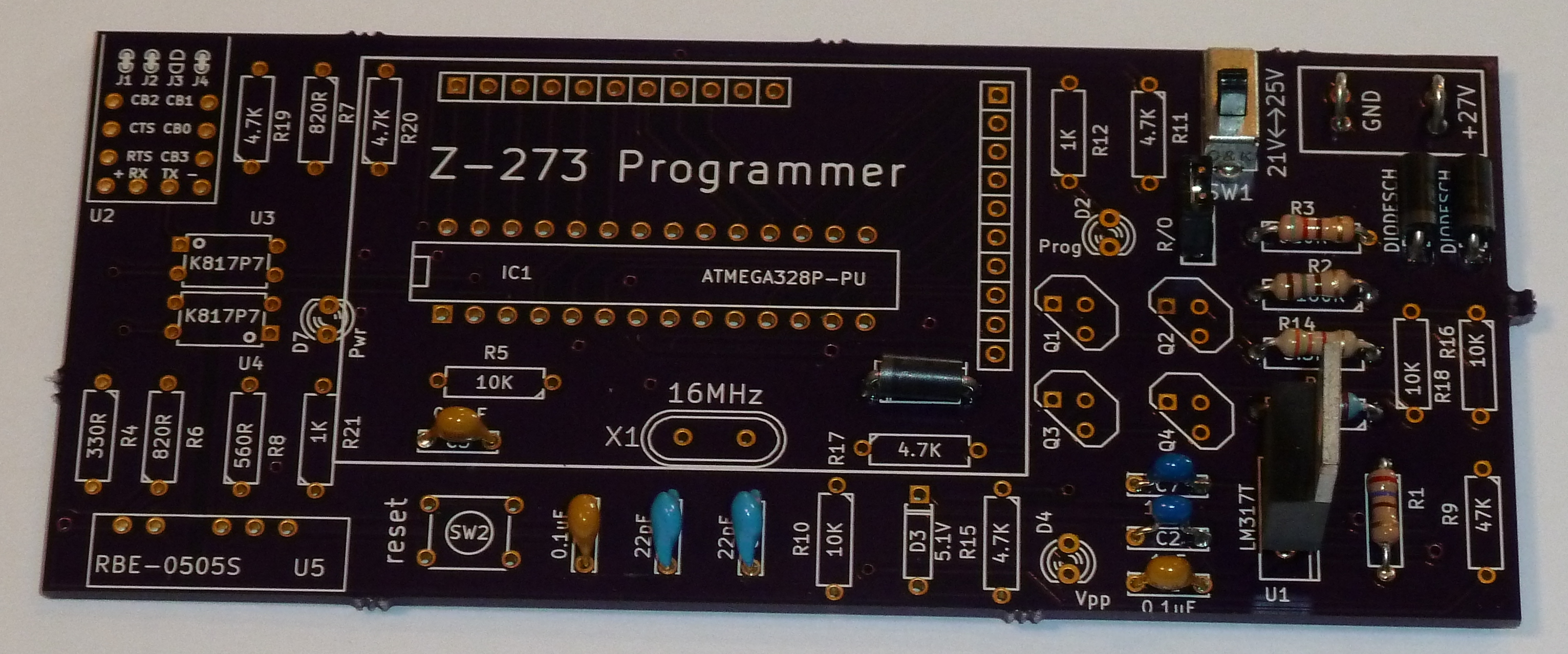
This programmer is fairly easy to construct from all through hole components. A bill of materials for this project is at http://www.mouser.com/ProjectManager/ProjectDetail.aspx?AccessID=1110b692f1 The circuit board is from OSH Park: https://oshpark.com/shared_projects/2IzMDawZ
This is the schematic diagram: schematic.pdf
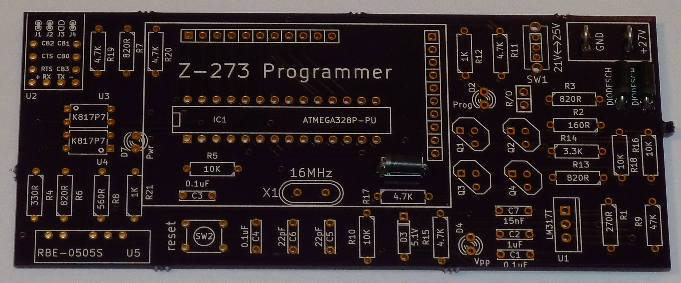
Begin by installing the Schottky diodes. There are three, and like all diodes direction matters. Match the stripe on the diode to the stripe on the silk screen. Trim the leads close to the board, and keep two leads to form the loops of our battery connection point.
Take two leads and bend them into a loop. I found that bending them around a #4 machine screw gave almost the right size. Then solder them into place in the top right corner of the board.
Your board should now look like the following picture. If you connect a battery pack on the loop connectors, you should have voltage at the striped side of the adjacent diodes.
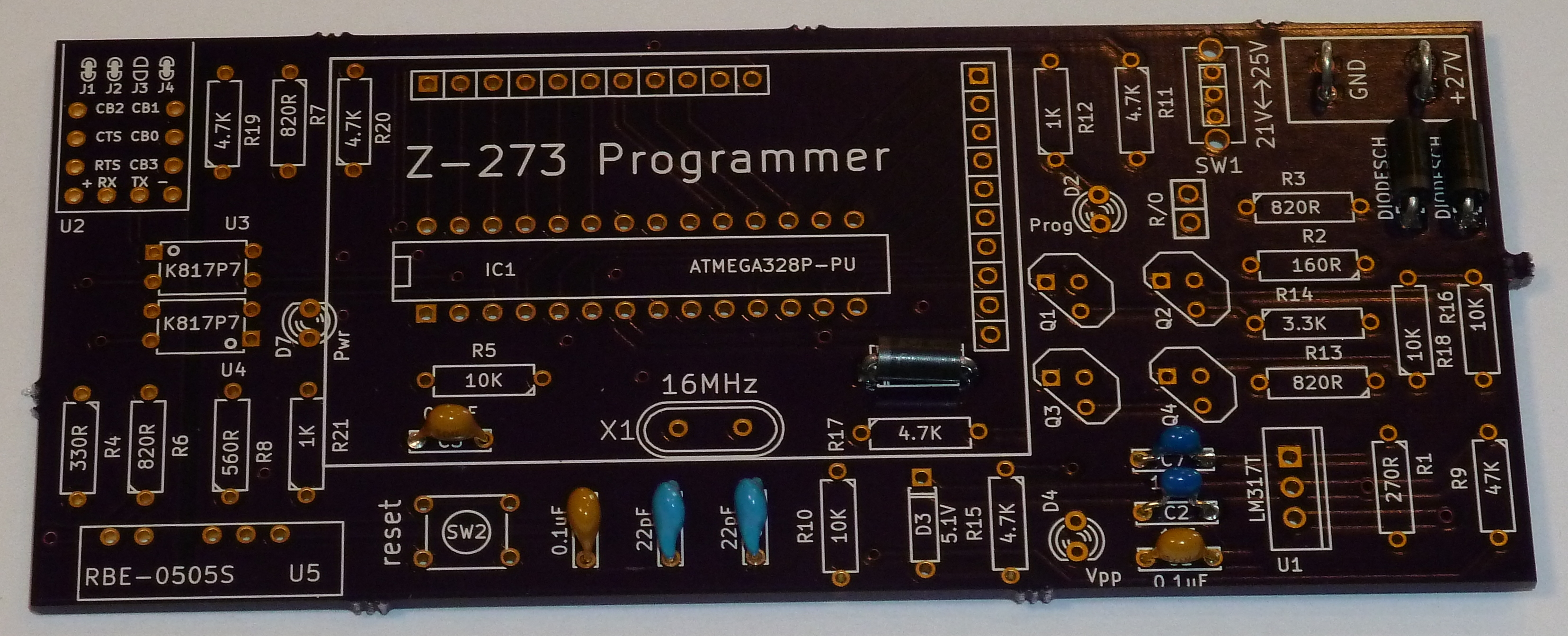
Now is a good time to attach all of the capacitors. All of the capacitors in this design are ceramic and direction does not matter.
High voltage circuit
The part of this design that requires the most care is the section that supplies the high voltage programming pin. This part of the circuit creates three distinct voltages, 5V, 21V, and 25V. We’ll create the 5V part first.
Install the LM317 voltage regulator. Direction matters, and the heat sink is visible on the silk screen. We’re also going to install R1, R13, and the read-only jumper. The ratio of these resistors determines the 5V voltage level. I recommend checking the resistance of these resistors to get close to 5V.
On this board, I used an R1 which measured 270 ohms and an R13 that measured 821 ohms. The formula for the LM317 is:
V = 1.25 ( 1 + R13/R1 )
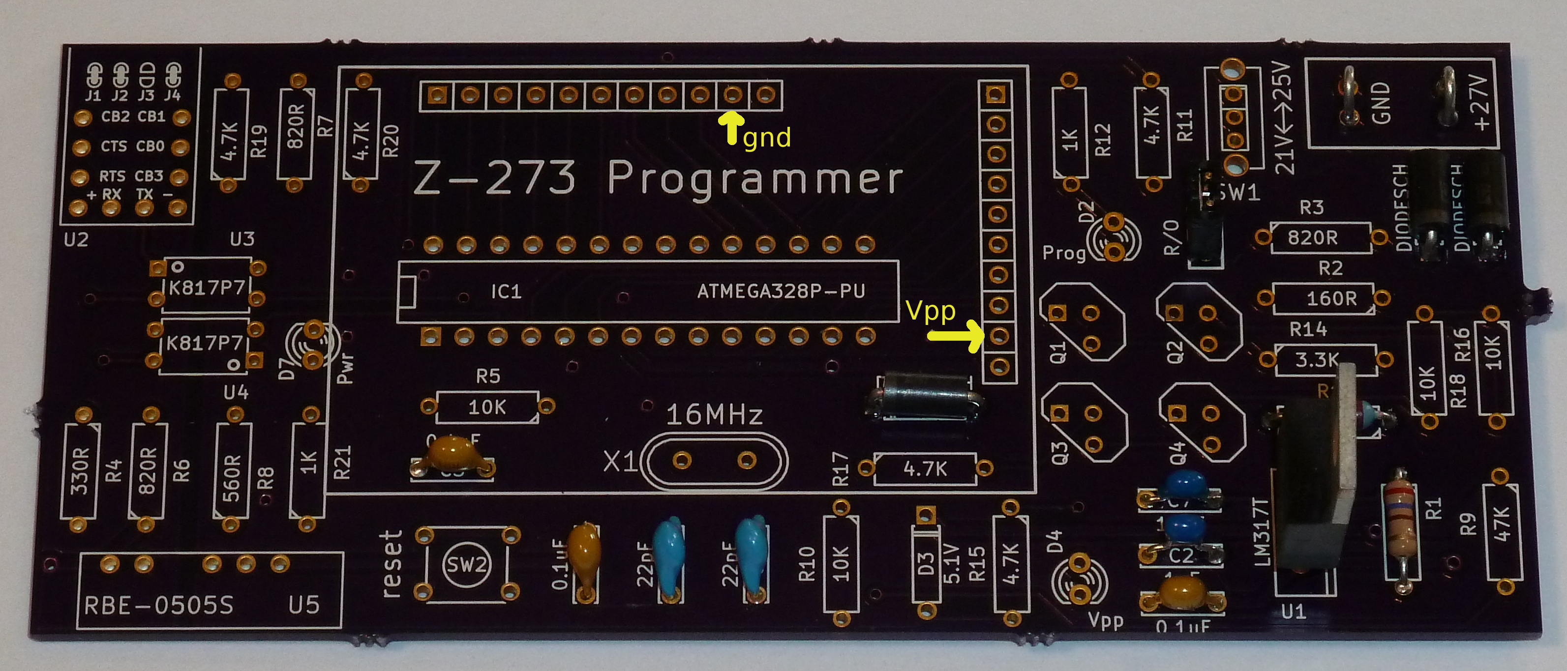
So, for my pair of resistors, I get 5.05V. Installed in circuit with the read-only jumper on and the battery pack connected, I can verify this voltage between ground and the Vpp pin.
Now, we add the 21V and 25V circuits. This means adding resistors R14, R2, and R3, as well as switch SW1. Again, I recommend actually checking the resistances of these resistors against the formula to get close to the desired voltages. For example, my 3.3K resistor R14 was actually more like 3.24K. I compensated by increasing R2 from 160 ohms to 180 ohms.
This makes my 21V calculation:
V = 1.25 ( 1 + (821 + 3240 + 180)/270 ) = 20.88V
My R3 resistor measured 821 ohms, making my 25V calculation come out:
V = 1.25 ( 1 + (821 + 3240 + 180 + 821)/270 ) = 24.69V
With the battery pack installed, I can verify each of these voltages between the GND pin and the Vpp pin. With the R/O jumper installed I should get 5V. With the jumper off I should get 21V or 25V according to the setting slide switch.
Everything else
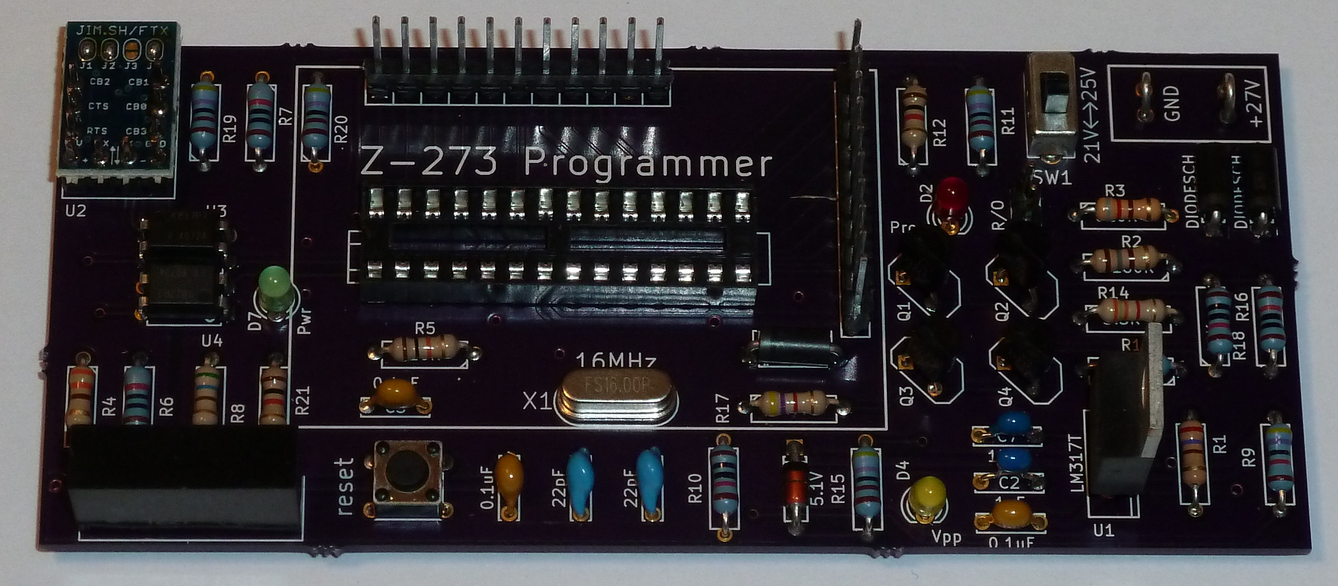
That is the hardest part of the build I think. The rest of the build should be routine. The LEDs have direction, being diodes, and the short leg of the diode should align with the flat side of the silk screen. If you install a diode backward it will fail to light up.
I would save the pin strip header for very last. To make sure it aligns well, I first install the pins into one of my z273 modules and then place the pins into the board. I like to have a lot of clearance, so I soldered the pins "high" in their holes, though it is hard to see in the next picture.
Cursory checks
I would do some testing of the board before installing a microcontroller chip. Verify at least that the RBE-0505S has 5V to the pins on each end. The green LED should light up when the USB is plugged in.
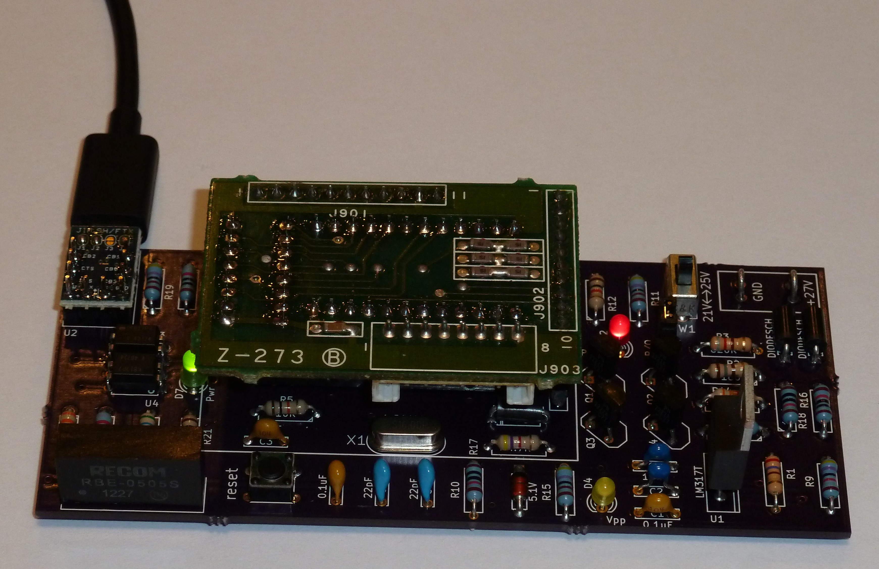
If that appears to work, unplug USB and install an Arduino chip with a Duemilanove bootloader and a copy of the z273 sketch.
Here’s a picture of the sketch attempting to program a z273 modules. As you can see, the programming LED is lit. But without the high voltage battery pack connected, no changes will be made. (And the Vpp LED is dark.)
Go back to the main page: index.html