Introduction
This page documents the programmer I designed for flashing the Z-273 module of older model Midland commercial radios. The intended audience for this project is ham radio operators who would like to convert a used commercial transciever to amateur use on amateur frequencies.
Before we begin
I think the key thing to think about when using my programmer is that EPROMs require over 20 volts for programming, but they are otherwise 5 volt devices. The Atmega ("Arduino") microcontroller that runs the show is also a 5 volt device. A USB port can deliver 5 volts, which is fine for reading or verifying an EPROM, but we’ll need another supply for programming it.
While designing and testing and generally messing around to create this board I blew through three or four Atmega chips, so my best recommendation overall is, "Don’t connect the 27V power, except when you actually want to program a chip. Disconnect it when the programming is complete."
The design of the programmer isolates the computer, but if you go poking around and short a 5V pin with the high voltage Vpp pin, you’ll blow your microcontroller as fast as you can blink, and probably your EPROM if it’s connected at the time.
Now that I’ve said that, I did try to protect you in as many ways as possible to prevent screwups caused by plugging or unplugging things wrong or in the wrong order. I put the microcontroller in a socket, so if you can’t resist poking around and you do blow it, you can replace it easily.
Okay, time for directions.
The board layout
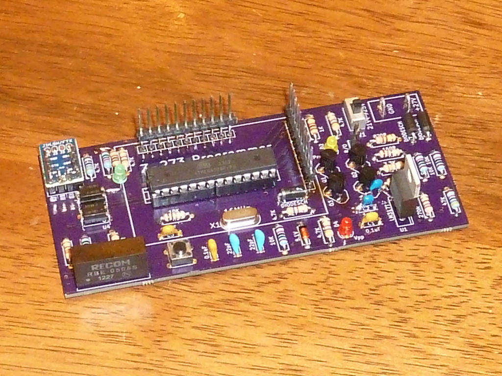
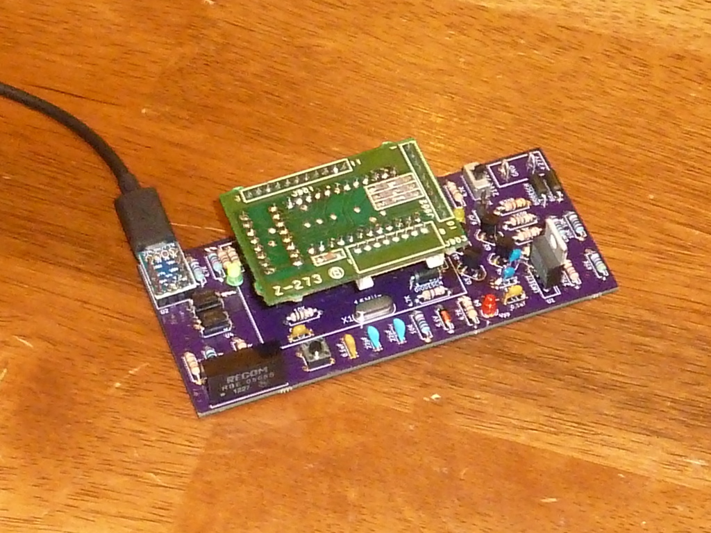
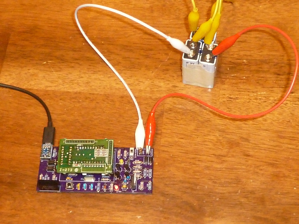
This is the programmer. It connects to the computer via a micro-USB cable at the small blue daughter card in the top left corner.
The center of the board has pins that match a Z-273 radio module. One of the errors in my first prototype board is that the holes weren’t drilled wide enough for the pins to pass through the board (you can see this in the picture), so these headers are surface-mounted. They’re pretty strong, but I’d use a bit of delicacy when removing modules if you have one of my prototypes, just in case. Wiggle, don’t yank.
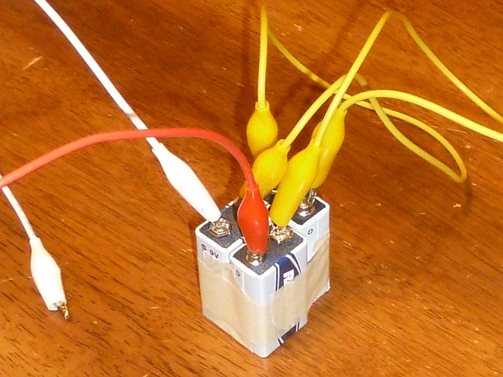
The top right corner of the card has a couple of loop "test points" for attaching a power pack to supply the programming voltage. When it is time to program new data, you’ll connect 27V to these points. I use three 9-volt batteries wired in series.
The single pushbutton at the bottom edge of the programmer resets the Arduino chip. You’ll need that for loading new sketches to the programmer.
Prerequisites
I’ve made use of programs that are readily available on GNU/Linux systems, like Ubuntu. You’ll want to make sure you have all of the necessary tools installed:
$ sudo apt-get install arduino sed vim-commonYou’ll probably need some kind of editor, and you may find it convenient to have an alternate serial communication program. If you use a DOS program to make changes to your EPROM images (DAT files), you may also need DOSBox.
$ sudo apt-get install gedit minicom dosboxReading a module
Reading and verifying an image can both be done with only 5 volt power, so no battery pack is needed. Attached your Z-273 module to the header, then plug the USB cable in.
The board will enumerate as a USB serial device, probably /dev/ttyUSB0 (though you can type dmesg in a terminal to check). We can talk to the board either through the Arduino serial monitor or using an alternate serial communication program like minicom.
Arduino serial monitor
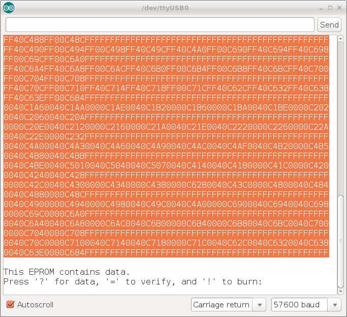
In the Arduino environment, choose Tools/Serial Monitor from the Arduino menu. In the lower status bar, choose "Carriage return" for your line ending and "57600 baud" for your speed. If you click "Send" with the programmer connected, you should see this response:
Press '?' for data, '=' to verify, and '!' to burn:Minicom
Alternatively, you can use minicom to talk to the programmer. To run minicom from a terminal, use a command like this:
$ minicom -b 57600 -D /dev/ttyUSB0If you hit the Enter key, you should see a message that looks like this:
Press '?' for data, '=' to verify, and '!' to burn:Reading data
Whichever communications method you use, if you send a question mark you should get back 64 lines of hex data. Highlight it with a mouse, and copy it into a text file. If you don’t have a favorite text editor, I recommend gedit. I’ll save my data as orig.hex.
We need to convert the hex data to binary data, and a command that can do that is xxd (this is why we need the vim-common package).
$ xxd -p -r orig.hex > orig.dat
$ ls -l orig.dat
If you check, you should find that orig.dat has exactly 2048 bytes, the precise size of our EPROM.
How you make changes to this DAT file to update the frequencies and settings will be up to you. There may be programs available online that can do that. Some of them are DOS programs that run well in DOSBox.
I’ve already included the Sample2m.dat (from the Yahoo MidlandLMR group) frequencies in my default Arduino sketch, if you wish to program those to a Z-273 module. It’s still a good idea to save the old data from the module before you erase it though.
Erasing an EPROM
You’ll need to put your EPROM under a UV lamp for a few minutes to erase it before you can write new data to it.
Writing data to the EPROM
I’ll cover later how to load new frequency data into the programmer. Basically, you’ll have to compile it into a new Arduino sketch, and use the Arduino environment to upload it to the programmer over the USB cable. For the moment, I’ll assume the Arduino chip has already been programmed.
After you have erased the Z-273 module with a UV lamp, load it into the programmer as before and read the data. Every byte should read as 0xFF, and at the end of the listing you should be told that the module is erased. If it still has some data, it’ll need more time under the UV light.
|
Note
|
Set your programming voltage before connecting your battery pack. There is a slide switch that will allow you to choose 21V or 25V for your programming voltage. I believe all Midland modules are 25V but I’ve found many program just fine with 21V (and if you’ve had to repair a module with a replacement EPROM, it might require 21V). |
When it’s time to program new data to the Z-273 module, connect a battery pack to the terminals. The Vpp LED should light up, giving you a visual indicator that high voltage is present. Send a ! to begin burning to the Z-273 module from the data stored in the Arduino sketch. You should see the Prog LED light up as the data is written.
When the write has finished, remove the programming voltage. Then send = to verify that the write was successful, and that it matches the data stored in the Arduino chip.
After you have verified the write, disconnect the USB power and remove the Z-273 module from the header to go back into the radio.
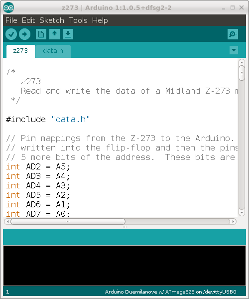
Unpacking the z273 sketch
The software that runs the programmer is an Arduino sketch called z273. It both controls the programmer to read and write data to the EPROM and contains a copy of the new data to be burned.
The first time you run the Arduino environment it will create your sketchbook in ~/sketchbook. You should also customize the "board" you’ll be using. Go to Tools/Board and select "Arduino Duemilanove w/ ATmega328." This will set the Arduino to program chips at a speed of 57600 bits per second, which matches the bootloader I use on the chip on the programmer.
|
Note
|
If you use an Atmega chip programmed with a bootloader for a different development card, then you should change the Tools/Board setting to match that. |
Exit the Arduino environment, and unpack my source code from z273.tar.gz.
$ cp z273.tar.gz ~/sketchbook
$ cd ~/sketchbook
$ tar xvzf z273.tar.gz
This should unpack the sketch into your Arduino sketchbook. If you start the Arduino environment again, you should be able to open it with File/Sketchbook/z273
Once the program is open, Ctrl-R should recompile it.
Uploading a new sketch
If you plug the programmer into the USB cable, then you can upload a newly compiled sketch by typing Ctrl-U.
The Arduino environment may ask you if you mean to use /dev/ttyUSB0 (or similar) for programming. You do. If it doesn’t ask, then it has probably already figured out what port to use.
Uploading a sketch will require that you press the reset button on your z273 programmer at just the right time. There is only one button on the programmer, and that’s what it is for, so you can’t miss it. I can always get the timing right each time if I do it this way:
-
hold in the reset button on the programmer
-
with my other hand type Ctrl-U to upload the sketch, and watch the progress bar (which shows the progress of recompiling the program before the upload begins)
-
let go of the reset button, just as the progress bar reaches 100%
If you get an error about the serial port being "not found," in my experience that comes from forgetting that you left minicom open and attached to the port in another window. The Arduino environment cannot upload a sketch while minicom has a "lock" on the serial port. To exit minicom type Ctrl-A Q in the terminal window where it is running.
If you get the timing right, there will be a short delay and then the status line in the Arduino environment will read "Done uploading." If you released the reset button too early or too late you may get synchronization errors, and you’ll just have to try again.
|
Note
|
If you set the wrong "board" under the Tools menu, you can also get synchronization errors. You want a setting that matches the bootloader on your Arduino chip. |
You can also remove the Arduino chip and program it in an Arduino programming card. This works fine; I just think you’ll eventually bend a pin if you remove the chip repeatedly for programming.
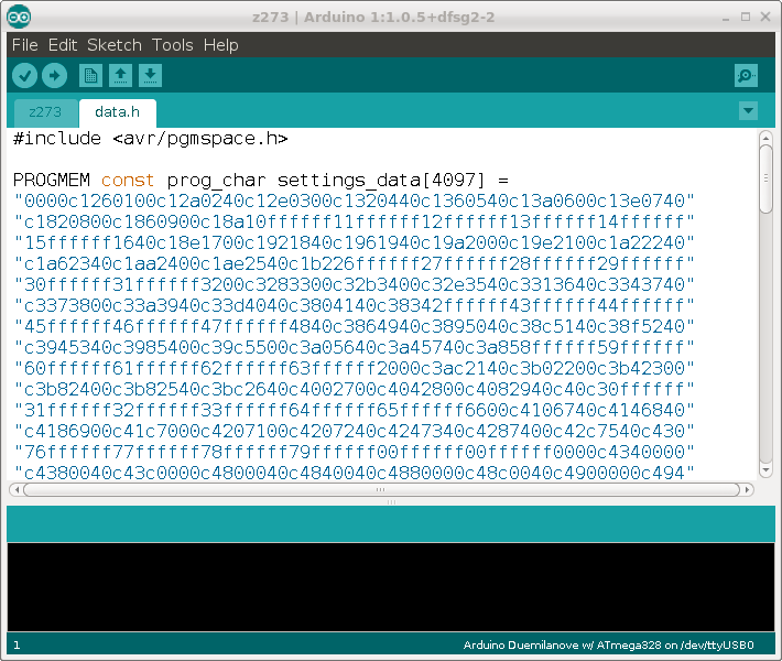
Updating the sketch with new frequencies
All of the frequencies in the program are stored in data.h, and if you inspect that file, you’ll see that it looks strikingly similar to the hex characters we dumped from the Z-273 module earlier. That’s because it is. It is just a little bit of Arduino code wrapped around a hex dump.
This is the only part of the Arduino sketch you should ever have to modify. For convenience, I’ve included a small script called dat2h that will build a new data.h for you from an existing DAT file. If you have new frequencies saved in a file called newfreq.dat, you would update your sketch like this:
$ cp newfreq.dat ~/sketchbook/z273
$ cd ~/sketchbook/z273
$ cp data.h data.h-old              # save a copy of the old data.h
$ ./dat2h newfreq.dat > data.h
Re-open the Arduino environment, recompile the program, and the new sketch will be ready to upload to the programmer (and from there you can instruct it to burn those frequencies into a blank Z-273 module just as before).
Back to [Don Bindner]