Link to PDF version: TinyMorseSchematic.pdf
As part of my interest in high altitude ballooning, I have experimented with different kinds of tracking systems. The best and most reliable tracking is probably APRS tracking from GPS receiver that accompanies your balloon payload. But balloon flights (their descents in particular) are chaotic events and are prone to equipment failure.
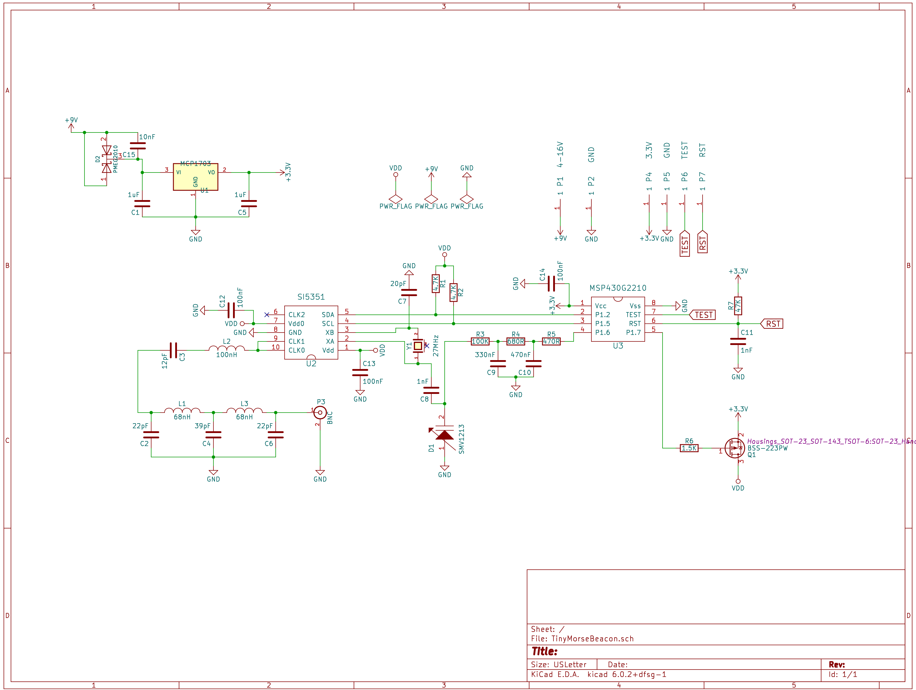
It is a good idea to have backup tracking methods on balloon flights, and to that end I have designed a variety of different beacon transmitters. The particular beacon documented here is based on the Si5351 programmable clock generator from Silicon Labs and the MSP430G2210 microcontroller from Texas Instruments. It is a low-power surface mount design that can be soldered by hand, and it will transmit for a couple of days from fresh set of AAA batteries.
Any clock generator can output continuous wave (CW) transmissions when low-pass filtered and fed to an antenna. Depending on voltage, the output power is fairly low (between 10mW and 13mW for this transmitter), but it works reliably. However, in the 2-meter band, where this transmitter operates, it is rare for people to use CW receivers. Most hand-held radios and most mobile radios expect FM modulation.
It is a fairly simple matter to coerce a clock generator to create FM modulated output by changing the frequency of its time base. In the following schematic, the time base of the SI5351 chip is provided by the 27MHz crystal, Y1. In order to vary the output of the generator, a varactor diode D1 is used to change the load capacitance on Y1.
Link to PDF version: TinyMorseSchematic.pdf
When transmitting, an audio morse code signal is generated on pin P1.6 of the MSP430 microcontroller and fed to D1, altering its capacitance. The effect is that Y1 varies slightly from 27MHz in frequency, and this translates into changes to the output frequency of the clock generator on pins CLK0 and CLK1. The result is an FM modulated signal that can be heard on a standard FM amateur radio receiver.
The board expects power from a battery pack and is intended to run on voltages between 4 volts and 9 volts. The MCP1703 voltage regulator provides 3.3V power to the components of the circuit, no matter what size battery pack is used.
The MSP430G2210 microcontroller is responsible for initializing the SI5351 clock generator. It does this via the I2C protocol on pins P1.2 (SDA) and P1.5 (SCL). Pin P1.7 of the microcontroller controls a MOSFET that switches power of the SI5351 (which is kept powered off except when transmitting in order to maximize battery life).
Pin P1.6 of the microcontroller is used to generate audio output for the FM modulation via pulse width modulation (PWM). The square wave output of this pin is fed through a low pass filter composed of resistors R3, R4, R5, and capacitors C9 and C10 to improve the quality of the audio.
The final output of the clock generator appears on pins CLK0 and CLK1 which are tied together before passing through a band-pass filter of inductor L2 and capacitor C3 and then a low-pass filter formed from inductors L1, L3 and capacitors C2, C4, and C6. The filtered output is sent to an SMA antenna connector at P3.
Using surface mount components, this transmitter fits on a 2-layer printed circuit board about the size of a stick of gum. Here is a rendering of the board.
![]()
And this is an image of an actual working board.
![]()
Gerber files suitable for commercial fabrication are available in: TinyMorseGerbers.zip
The C microcontroller code for this transmitter has three functions:
Since the microcontroller has a limited amount of ram, a bit of Python code is used to generate the dots and dashes of the actual audio Morse code message. The Python code generates C data structures for the message payload and call sign that are then compiled into the final microcontroller binary. It is necessary to modify the Python code with your personal call sign before generating a new microcontroller firmware.
This code defaults to a transmitter frequency of 146.565MHz, though depending on the characteristics of your particular board it may be slightly off frequency. If you find that to be the case, it may be necessary to generate a new register_map.h file for the Si5351 chip using the ClockBuilder Pro program available for download from Skyworks.
The code is released under the GPL v3.0.
My GitLab: https://gitlab.com/donbindner/tinymorsebeacon
Return to: [Don Bindner]