1. Prepping for the MSP430
It took about a week for my MSP430 Launchpad to arrive after I ordered it from TI. That gave me time to make sure my Linux system would work with the hardware. The udev system needs to be made aware of the Launchpad, so I added this file: /etc/udev/rules.d/46-TI_launchpad.rules on my Ubuntu Lucid system:
ATTRS{idVendor}=="0451", ATTRS{idProduct}=="f430", MODE="660", GROUP="plugdev"
ATTRS{idVendor}=="0451", ATTRS{idProduct}=="f432", MODE="660", GROUP="plugdev"
A quick restart udev as root, and my system was ready to recognize the Launchpad.
I also made sure that my personal user account was in the plugdev group in /etc/group, so I’d have read and write access to /dev/ttyACM0 when the board is plugged in. It was already.
For compiling, I installed mspgcc4 from http://sourceforge.net/projects/mspgcc4/files/ . It takes a long time to build mspgcc4, but otherwise the install was pretty painless.
I learned that I’d also want mspdebug for communicating with the board and installing newly compiled programs. So I built that from the source at http://sourceforge.net/projects/mspdebug/files/ . It also installed smoothly.
Then it was just a matter of waiting for my board to arrive.
2. Out of the box
March 11, 2011. My Launchpad came today. I’d watched the demo video, so naturally I tried the experiment where you rub on the chip to make it warmer. But what I really wanted to do is write some of my own code and program it to a chip. So I swapped out the pre-recorded chip for the msp430g2211 that comes in the non-static envelope. I went off to find a Hello World program.
As I understand it, in the world of microcontrollers, Hello World programs blink and LED on and off. Well, conveniently, the Launchpad has two LEDs built into the support board. One is on pin 0 and the other is on pin 6.
|
|
I’m planning to do my development on my Linux laptop with mspgcc4, so I set off to find a simple C program to compile and send to the chip. |
After a bit, I ran across something similar, but not quite exactly like this.
#include <io.h>

#define pin6mask  (0x01 << 6)

int main(void) {
    /* Hold the watchdog timer so it doesn't reset our chip */
    WDTCTL = WDTPW + WDTHOLD;

    /* Configure all pins on port 1 as output pins */
    P1DIR = 0xff;

    /* Set pin 6 high.  Basically, this command sets any combination
     * of the pins on port 1 high.  Pin 0 is 2^0, pin 1 is 2^2, etc.
     * Values can be binary or'd together. Other pins are low.
     */
    P1OUT = pin6mask;

    /* infinite loop */
    for( ; ; ) {
        /* The following two lines implement a very crude delay loop.
         * The actual length of the delay can vary significantly.
         * This approach may not work with all compilers.
         */
        volatile int i;
        for( i = 0; i < 20000; i++ );

        /* Toggle the state of pin 6 on port 1 by exclusive or'ing with
           the mask that represents that pin. */
        P1OUT = P1OUT ^ pin6mask;
    }
}|
|
The line that says WDTCTL = WDTPW + WDTHOLD should be read as, "access the watchdog timer control without password and hold the counter." My msp430g2211 didn’t seem to reset when I left this line out, but some chips in the series apparently will. |
I compiled it, and installed it to my Launchpad with mspdebug.
$ msp430-gcc -mmcu=msp430x2211 -o hello.elf hello.c

$ mspdebug rf2500
(mspdebug) prog hello.elf
Erasing...
Programming...
Writing 106 bytes to f800...
Writing  32 bytes to ffe0...
(mspdebug) run
Running. Press Ctrl+C to interrupt...
^C
...
(mspdebug) ^D
Blink. Blink. Blink. Hello, world!
3. Blinking lights number 2
There are two LEDs on the board, so lets make a small change to blink both of them! While, we’re making changes, we’ll try to be a little more subtle. This time we’ll only set the pins we want to actually use as output pins.
#include <io.h>

#define pin0mask  (0x01 << 0)
#define pin6mask  (0x01 << 6)

int main(void) {
    /* Hold the watchdog timer so it doesn't reset our chip */
    WDTCTL = WDTPW + WDTHOLD;

    /* Configure pins 0,6 on port 1 as output pins */
    P1DIR = pin0mask | pin6mask;

    /* Set pin 6 high.  Basically, this command sets any combination
     * of the pins on port 1 high.  Pin 0 is 2^0, pin 1 is 2^2, etc.
     * Values can be binary or'd together. Other pins are low.
     */
    P1OUT = pin6mask;

    /* infinite loop */
    for( ; ; ) {
        /* The following two lines implement a very crude delay loop.
         * The actual length of the delay can vary significantly.
         * This approach may not work with all compilers.
         */
        volatile int i;
        for( i = 0; i < 20000; i++ );

        /* Toggle the state of pins 0,6 on port 1 by exclusive or'ing with
           the mask that represents those pins. */
        P1OUT = P1OUT ^ (pin0mask | pin6mask);
    }
}
It’s clear that we’re going to be compiling and installing object code repeatedly. This can be done in a single step by a command similar to this:
$ msp430-gcc -mmcu=msp430x2211 -o hello.elf hello.c && mspdebug rf2500 'prog hello.elf'The way to think of this command is, "Compile the source, and, if successful, run mspdebug to program the object code to the Launchpad."
4. Pushbutton fun
The Launchpad board has two pushbuttons. One is hooked to reset, so we might not be able to access that (I don’t know yet). But the other one is hooked to pin 3, and we can definitely check that. It turns out that pin 3 is high when the button is not pushed and goes low when we press it.
We can use that to change the behavior of our lights. Let’s blink only the red light when the button is down and blink both lights (not necessarily alternately as you’ll see) when the button is up.
#include <io.h>

#define pin0mask  (0x01 << 0)
#define pin3mask  (0x01 << 3)
#define pin6mask  (0x01 << 6)

int main(void) {
    /* Hold the watchdog timer so it doesn't reset our chip */
    WDTCTL = WDTPW + WDTHOLD;

    /* Configure pins 0,6 on port 1 as output pins */
    P1DIR = pin0mask | pin6mask;

    /* Set pin 6 high.  Basically, this command sets any combination
     * of the pins on port 1 high.  Pin 0 is 2^0, pin 1 is 2^2, etc.
     * Values can be binary or'd together. Other pins are low.
     */
    P1OUT = pin6mask;

    /* infinite loop */
    for( ; ; ) {
        /* The following two lines implement a very crude delay loop.
         * The actual length of the delay can vary significantly.
         * This approach may not work with all compilers.
         */
        volatile int i;
        for( i = 0; i < 20000; i++ );

        /* Switch 2 is connected to pin 3.  If it is low, then change the
         * blinking behavior.  Sometimes we blink both LEDs, sometimes only
         * the red LED.
         */
        if(( P1IN & pin3mask ) == 0 ) {
            /* Toggle just pin 0. */
            P1OUT ^= pin0mask;
        } else {
            /* Toggle both pin 0 and pin 6 */
            P1OUT ^= pin0mask|pin6mask;
        }
    }
}
When you press switch 2 (which is connected to pin 3) the green LED will quit changing state, and only the red LED will flash. When you release the button, both will flash again (though whether they alternate or not depends on the timing of your button release).
5. More pretty lights
How about a program that knows severals blink patterns? This program knows "red only" and "green only" and "both together" and "both alternately." For your enjoyment:
#include <io.h>

#define pin0mask  (0x01 << 0)
#define pin3mask  (0x01 << 3)
#define pin6mask  (0x01 << 6)

int main(void) {
    /* Hold the watchdog timer so it doesn't reset our chip */
    WDTCTL = WDTPW + WDTHOLD;

    /* Configure pins 0,6 on port 1 as output pins */
    P1DIR = pin0mask | pin6mask;

    /* a flag to tell us when we've handled a button event */
    int buttonPushed = 0;

    /* we'll toggle between different modes */
    int blinkMode = 0;

    /* which lights we need to blink -- start red only */
    int blinkMask = pin0mask;

    /* make sure green (pin 6) is turned off */
    P1OUT &= ~pin6mask;

    /* infinite loop */
    for( ; ; ) {
        /* The following two lines implement a very crude delay loop.
         * The actual length of the delay can vary significantly.
         * This approach may not work with all compilers.
         */
        volatile int i;
        for( i = 0; i < 20000; i++ );

        /* Switch 2 is connected to pin 3.  If it is low, then change the
         * blinking behavior (unless it we have handled the press already)
         */
        if(( P1IN & pin3mask ) == 0 ) {
            if( !buttonPushed ) {
                /* remember so we don't try to handle this press again */
                buttonPushed = 1;

                blinkMode = (blinkMode + 1)%4;

                if( blinkMode == 0 ) {
                    /* blink red (bit 0) only */
                    blinkMask = pin0mask;

                    /* make sure (pin 6) green is off */
                    P1OUT &= ~pin6mask;
                } else if( blinkMode == 1 ) {
                    /* blink green (pin 6) only */
                    blinkMask = pin6mask;

                    /* make sure red (pin 0) is off */
                    P1OUT &= ~pin0mask;
                } else if( blinkMode == 2 ) {
                    /* blink both together */
                    blinkMask = pin0mask|pin6mask;

                    /* make sure both are on */
                    P1OUT |= pin0mask|pin6mask;
                } else {
                    /* blink both alternately */
                    blinkMask = pin0mask|pin6mask;

                    /* make sure red is off and green is on */
                    P1OUT &= ~pin0mask;
                    P1OUT |= pin6mask;
                }
            }
        } else {
            buttonPushed = 0;
        }

        P1OUT ^= blinkMask;
    }
}
You might notice that it misses some key presses if you are very quick. That’s because it won’t notice a key press (or a key release) during the delay loop. This program might be improved a bit by putting the key detection into the loop. The next version does just that.
#include <io.h>

#define pin0mask  (0x01 << 0)
#define pin3mask  (0x01 << 3)
#define pin6mask  (0x01 << 6)

int main(void) {
    /* Hold the watchdog timer so it doesn't reset our chip */
    WDTCTL = WDTPW + WDTHOLD;

    /* Configure pins 0,6 on port 1 as output pins */
    P1DIR = pin0mask | pin6mask;

    /* a flag to tell us when we've handled a button event */
    int buttonPushed = 0;

    /* we'll toggle between different modes */
    int blinkMode = 0;

    /* which lights we need to blink -- start red only */
    int blinkMask = pin0mask;

    /* make sure green (pin 6) is turned off */
    P1OUT &= ~pin6mask;

    /* infinite loop */
    for( ; ; ) {
        int j;
        /* delay while watching for button presses */
        for( j = 0; j < 100; j++ ) {
            /* The following two lines implement a very crude delay loop.
             * The actual length of the delay can vary significantly.
             * This approach may not work with all compilers.
             */
            volatile int i;
            for( i = 0; i < 200; i++ );

            /* Switch 2 is connected to pin 3.  If it is low, then change the
             * blinking behavior (unless it we have handled the press already)
             */
            if(( P1IN & pin3mask ) == 0 ) {
                if( !buttonPushed ) {
                    /* remember so we don't try to handle this press again */
                    buttonPushed = 1;

                    blinkMode = (blinkMode + 1)%4;

                    if( blinkMode == 0 ) {
                        /* blink red (bit 0) only */
                        blinkMask = pin0mask;

                        /* make sure green (pin 6) is off */
                        P1OUT &= ~pin6mask;
                    } else if( blinkMode == 1 ) {
                        /* blink green (pin 6) only */
                        blinkMask = pin6mask;

                        /* make sure red (pin 0) is off */
                        P1OUT &= ~pin0mask;
                    } else if( blinkMode == 2 ) {
                        /* blink both together */
                        blinkMask = pin0mask|pin6mask;

                        /* make sure both are on */
                        P1OUT |= pin0mask|pin6mask;
                    } else {
                        /* blink both alternately */
                        blinkMask = pin0mask|pin6mask;

                        /* make sure red is off and green is on */
                        P1OUT &= ~pin0mask;
                        P1OUT |= pin6mask;
                    }
                }
            } else {
                buttonPushed = 0;
            }
        }

        /* blink the lights */
        P1OUT ^= blinkMask;
    }
}
6. Community Coding Style
If you read much code written by the MSP430 community, you’ll notice a couple of differences from the code I have written. Two things in particular stand out to me. Where I have use names for constants like pin0mask, most code will use pre-defined constants, like BIT0.
The other difference is that where I have used #include <io.h>, other source files will often include a header file for the specific version of the MSP430 microcontroller they are targeting. Since I’m currently writing for the msp430g2211, I could have written #include <msp430g2211.h>.
Another subtle difference is that rather than using or to combine bitmasks, most of the community code uses plus. For example, where I might have been inclined to write BIT0 | BIT6, you will instead see BIT0 + BIT6. Since the bitmasks are non-overlapping binary numbers, it really doesn’t make any difference.
With these changes, our most recent program would look like:
#include <msp430g2211.h>

int main(void) {
    /* Clear and hold the watchdog timer so it doesn't reset our chip */
    WDTCTL = WDTPW + WDTHOLD;

    /* Configure pins 0,6 on port 1 as output pins */
    P1DIR = BIT0 + BIT6;

    /* a flag to tell us when we've handled a button event */
    int buttonPushed = 0;

    /* we'll toggle between different modes */
    int blinkMode = 0;

    /* which lights we need to blink -- start red only */
    int blinkMask = BIT0;

    /* make sure green (pin 6) is turned off */
    P1OUT &= ~BIT6;

    /* infinite loop */
    for( ; ; ) {
        int j;
        /* delay while watching for button presses */
        for( j = 0; j < 100; j++ ) {
            /* The following two lines implement a very crude delay loop.
             * The actual length of the delay can vary significantly.
             * This approach may not work with all compilers.
             */
            volatile int i;
            for( i = 0; i < 200; i++ );

            /* Switch 1 is connected to pin 3.  If it is low, then change the
             * blinking behavior (unless it we have handled the press already)
             */
            if(( P1IN & BIT3 ) == 0 ) {
                if( !buttonPushed ) {
                    /* remember so we don't try to handle this press again */
                    buttonPushed = 1;

                    blinkMode = (blinkMode + 1)%4;

                    if( blinkMode == 0 ) {
                        /* blink red (bit 0) only */
                        blinkMask = BIT0;

                        /* make sure green (pin 6) is off */
                        P1OUT &= ~BIT6;
                    } else if( blinkMode == 1 ) {
                        /* blink green (pin 6) only */
                        blinkMask = BIT6;

                        /* make sure red (pin 0) is off */
                        P1OUT &= ~BIT0;
                    } else if( blinkMode == 2 ) {
                        /* blink both together */
                        blinkMask = BIT0 + BIT6;

                        /* make sure both are on */
                        P1OUT |= BIT0 + BIT6;
                    } else {
                        /* blink both alternately */
                        blinkMask = BIT0 + BIT6;

                        /* make sure red is off and green is on */
                        P1OUT &= ~BIT0;
                        P1OUT |= BIT6;
                    }
                }
            } else {
                buttonPushed = 0;
            }
        }

        /* blink the lights */
        P1OUT ^= blinkMask;
    }
}
Since the proper microcontroller is specified in the source code, it is no longer necessary to specify it during the compile step. To build this code, we can simply do:
$ msp430-gcc -o hello.elf hello.cThis builds a program that is ready to be programmed to the chip. If we want to build the binary and program the chip in one step, we can use:
$ msp430-gcc -o hello.elf hello.c && mspdebug rf2500 'prog hello.elf'People don’t always agree on what makes some code simpler or easier to understand than other code. As a beginner, I found that being explicit about the idea of bitmasks in my variable names felt easier. In general, though, I think it makes sense to adopt the conventions of the community around you. To that end, it seems sensible to:
-
Use
#import <io.h>when developing programs when you have no specific microcontroller in mind (like tutorials?), and import the relevant header file when targeting a particular chip. -
Use the standard names already available to you for bitmasks and important constants, because that is what people are accustomed to seeing.
-
Use + to combine bitmasks.
You can discover the names of the relevant header files where you installed your compiler. For example, I installed in /opt/msp430-gcc-4.4.5, and this is a list of the different header files:
$ ls $ ls /opt/msp430-gcc-4.4.5/msp430/include/
bits/           msp430f148.h   msp430f437.h    msp430f5514.h   msp430p337.h
byteswap.h      msp430f1491.h  msp430f438.h    msp430f5515.h   msp430x09x.h
cc430f5133.h    msp430f149.h   msp430f439.h    msp430f5517.h   msp430x11x1.h
cc430f5135.h    msp430f155.h   msp430f447.h    msp430f5519.h   msp430x11x2.h
cc430f5137.h    msp430f156.h   msp430f4481.h   msp430f5521.h   msp430x11x.h
cc430f6125.h    msp430f157.h   msp430f448.h    msp430f5522.h   msp430x12x2.h
cc430f6126.h    msp430f1610.h  msp430f4491.h   msp430f5524.h   msp430x12x.h
cc430f6127.h    msp430f1611.h  msp430f449.h    msp430f5525.h   msp430x13x1.h
cc430f6135.h    msp430f1612.h  msp430f46161.h  msp430f5526.h   msp430x13x.h
cc430f6137.h    msp430f167.h   msp430f4616.h   msp430f5527.h   msp430x14x1.h
cc430x513x.h    msp430f168.h   msp430f46171.h  msp430f5528.h   msp430x14x.h
cc430x612x.h    msp430f169.h   msp430f4617.h   msp430f5529.h   msp430x15x.h
cc430x613x.h    msp430f2001.h  msp430f46181.h  msp430f5630.h   msp430x16x.h
ctype.h         msp430f2002.h  msp430f4618.h   msp430f5631.h   msp430x20x1.h
debug.h         msp430f2003.h  msp430f46191.h  msp430f5632.h   msp430x20x2.h
endian.h        msp430f2011.h  msp430f4619.h   msp430f5633.h   msp430x20x3.h
errno.h         msp430f2012.h  msp430f47126.h  msp430f5634.h   msp430x21x1.h
in430.h         msp430f2013.h  msp430f47127.h  msp430f5635.h   msp430x21x2.h
inttypes.h      msp430f2101.h  msp430f47163.h  msp430f5636.h   msp430x22x2.h
io.h            msp430f2111.h  msp430f47166.h  msp430f5637.h   msp430x22x4.h
iomacros.h      msp430f2112.h  msp430f47167.h  msp430f5638.h   msp430x23x0.h
isr_compat.h    msp430f2121.h  msp430f47173.h  msp430f6630.h   msp430x23x.h
limits.h        msp430f2122.h  msp430f47176.h  msp430f6631.h   msp430x241x.h
math.h          msp430f2131.h  msp430f47177.h  msp430f6632.h   msp430x24x1.h
msp430c091.h    msp430f2132.h  msp430f47183.h  msp430f6633.h   msp430x24x.h
msp430c092.h    msp430f2232.h  msp430f47186.h  msp430f6634.h   msp430x26x.h
msp430c1111.h   msp430f2234.h  msp430f47187.h  msp430f6635.h   msp430x31x.h
msp430c111.h    msp430f2252.h  msp430f47193.h  msp430f6636.h   msp430x32x.h
msp430c1121.h   msp430f2254.h  msp430f47196.h  msp430f6637.h   msp430x33x.h
msp430c112.h    msp430f2272.h  msp430f47197.h  msp430f6638.h   msp430x415.h
msp430c1331.h   msp430f2274.h  msp430f477.h    msp430fe4232.h  msp430x417.h
msp430c1351.h   msp430f2330.h  msp430f4783.h   msp430fe423a.h  msp430x41x2.h
msp430c311s.h   msp430f233.h   msp430f4784.h   msp430fe423.h   msp430x41x.h
msp430c312.h    msp430f2350.h  msp430f478.h    msp430fe4242.h  msp430x42x0.h
msp430c313.h    msp430f235.h   msp430f4793.h   msp430fe4252.h  msp430x42x.h
msp430c314.h    msp430f2370.h  msp430f4794.h   msp430fe425a.h  msp430x43x1.h
msp430c315.h    msp430f2410.h  msp430f479.h    msp430fe425.h   msp430x43x.h
msp430c323.h    msp430f2416.h  msp430f5131.h   msp430fe4272.h  msp430x44x1.h
msp430c325.h    msp430f2417.h  msp430f5132.h   msp430fe427a.h  msp430x44x.h
msp430c336.h    msp430f2418.h  msp430f5151.h   msp430fe427.h   msp430x461x1.h
msp430c337.h    msp430f2419.h  msp430f5152.h   msp430fg4250.h  msp430x46x.h
msp430c412.h    msp430f2471.h  msp430f5171.h   msp430fg4260.h  msp430x471x3.h
msp430c413.h    msp430f247.h   msp430f5172.h   msp430fg4270.h  msp430x471x6.h
msp430cg4616.h  msp430f2481.h  msp430f5304.h   msp430fg437.h   msp430x471x7.h
msp430cg4617.h  msp430f248.h   msp430f5308.h   msp430fg438.h   msp430x47x3.h
msp430cg4618.h  msp430f2491.h  msp430f5309.h   msp430fg439.h   msp430x47x4.h
msp430cg4619.h  msp430f249.h   msp430f5310.h   msp430fg4616.h  msp430x47x.h
msp430e112.h    msp430f2616.h  msp430f5418a.h  msp430fg4617.h  msp430x54xa.h
msp430e313.h    msp430f2617.h  msp430f5418.h   msp430fg4618.h  msp430x54x.h
msp430e315.h    msp430f2618.h  msp430f5419a.h  msp430fg4619.h  msp430x551x.h
msp430e325.h    msp430f2619.h  msp430f5419.h   msp430fg477.h   msp430x552x.h
msp430e337.h    msp430f412.h   msp430f5435a.h  msp430fg478.h   msp430xe42x2.h
msp430f1101a.h  msp430f4132.h  msp430f5435.h   msp430fg479.h   msp430xe42xa.h
msp430f1101.h   msp430f413.h   msp430f5436a.h  msp430fw423.h   msp430xe42x.h
msp430f110.h    msp430f4152.h  msp430f5436.h   msp430fw425.h   msp430xg42x0.h
msp430f1111a.h  msp430f415.h   msp430f5437a.h  msp430fw427.h   msp430xg43x.h
msp430f1111.h   msp430f417.h   msp430f5437.h   msp430g2001.h   msp430xg46x.h
msp430f1121a.h  msp430f423a.h  msp430f5438a.h  msp430g2101.h   msp430xg47x.h
msp430f1121.h   msp430f423.h   msp430f5438.h   msp430g2111.h   msp430xw42x.h
msp430f1122.h   msp430f4250.h  msp430f5500.h   msp430g2121.h   setjmp.h
msp430f112.h    msp430f425a.h  msp430f5501.h   msp430g2131.h   signal.h
msp430f1132.h   msp430f425.h   msp430f5502.h   msp430g2201.h   stdint.h
msp430f1222.h   msp430f4260.h  msp430f5503.h   msp430g2211.h   stdio.h
msp430f122.h    msp430f4270.h  msp430f5504.h   msp430g2221.h   stdlib.h
msp430f1232.h   msp430f427a.h  msp430f5505.h   msp430g2231.h   string.h
msp430f123.h    msp430f427.h   msp430f5506.h   msp430l092.h    sys/
msp430f133.h    msp430f4351.h  msp430f5507.h   msp430p112.h    xms430f5438.h
msp430f135.h    msp430f435.h   msp430f5508.h   msp430p313.h
msp430f1471.h   msp430f4361.h  msp430f5509.h   msp430p315.h
msp430f147.h    msp430f436.h   msp430f5510.h   msp430p315s.h
msp430f1481.h   msp430f4371.h  msp430f5513.h   msp430p325.h
This is how I discovered that the correct include file would be msp430g2211.h. To see the contents of this header file (to learn, for example, the names of important constants), I used:
$ less /opt/msp430-gcc-4.4.5/msp430/include/msp430g2211.h7. Button triggered interrupts
I don’t entirely know what I’m doing with regard to interrupt programming on the MSP430 yet, but I have cobbled together a working program based on some demo code (translating it so it will compile with mspgcc4). It toggles the LEDs off and on when you press switch 2.
/* Adapted from Aldo Briano's demo code */
#include <msp430g2211.h>

#define RED_LED BIT0
#define GRN_LED BIT6
#define BUTTON  BIT3

int main(void)
{
    /* Stop the watchdog timer so it doesn't reset our chip */
    WDTCTL = WDTPW + WDTHOLD;

    /* Set both LED pins as output pins (and the rest are input pins) */
    P1DIR = (RED_LED + GRN_LED);

    /* Make sure both LEDs are off */
    P1OUT &= ~(RED_LED + GRN_LED);

    /* "Port 1 interrupts enable" for our BUTTON pin */
    P1IE |= BUTTON;

    /* Clear our BUTTON in the Port 1 interrupt flag.
     * This would be more important if our program handled
     * different kinds of interrupts, because we'd need
     * to check this flag to see which of the interrupts
     * were actually triggered.
     */
    P1IFG &= ~BUTTON;

    /* loop forever */
    for( ; ; ) {
        /* Go into low power mode 0, general interrupts enabled */
        __bis_SR_register( LPM0_bits + GIE );
    }
}


/* Port 1 interrupt service routine.  First, this prototype tells
 * the compiler that the function handles interrupts for
 * Port 1.  Then the function follows.
 */
void Port_1 (void) __attribute__((interrupt(PORT1_VECTOR)));
void Port_1(void)
{
    /* Toggle both LEDs by xoring with their bitmasks */
    P1OUT ^= (RED_LED + GRN_LED);

    /* Clear the interrupt flag */
    P1IFG &= ~BUTTON; // P1.3 IFG cleared

    /* Uncomment the next line if you want button releases also to trigger.
     * That is, we change the interrupt edge, and Hi-to-Low will
     * trigger the next interrupt.
     */
    // P1IES ^= BUTTON;

    /* This line is still magic to me.  I think it exits low power mode 0
     * so the main program can resume running.
     */
    __bic_SR_register_on_exit( LPM0_bits );
}
8. Hello World revisited
8.1. Internal watchdog timer
I’ve always felt that the original Hello World was sort of weak. It worked, and managed to blink the LED succussfully, but I knew it wasn’t the "right" approach. The right approach would have used the Watchdog Timer to trigger the blinks.
I eventually found some code I think I understand, and I have a new Hello World for the MSP430.
#include <msp430g2211.h>

#define RED_LED BIT0

unsigned int wdtCounter = 0;

void main(void)
{
    /* Set watchdog timer interval to 32ms */
    WDTCTL = WDT_MDLY_32;

    /* "Interrupt enable 1" for the Watchdog Timer interrupt */
    IE1 |= WDTIE;

    /* Set the LED pin as an output pin */
    P1DIR |= RED_LED;

    /* Turn on LED pin */
    P1OUT |= RED_LED;

    /* Go into low power mode 0, general interrupts enabled */
    __bis_SR_register( LPM0_bits + GIE );

    /* Do nothing...forever */
    for( ; ; ) { }
}

/* Watchdog Timer interrupt service routine.  The function prototype
 * tells the compiler that this will service the Watchdog Timer, and
 * then the function follows.
 */
void watchdog_timer(void) __attribute__((interrupt(WDT_VECTOR)));
void watchdog_timer(void)
{
    wdtCounter++;

    /* Count 32 interrupts x 32ms = 1024ms, or about one second */
    if(wdtCounter == 32) {
        /* Toggle the LED pin */
        P1OUT ^= RED_LED;

        /* Reset the counter for the next blink */
        wdtCounter = 0;
    }

    /* Go back to low power mode 0 until the next interrupt */
    __bis_SR_register_on_exit( LPM0_bits );
}
One subtle thing about this interrupt handler that isn’t obviously different than the previous one (without careful inspection) is the exit method. Previously, we used __bic_SR_register_on_exit to return, and this time we used __bis_SR_register_on_exit. If we clear the low power mode bits, the microcontroller will resume running the main program (and that is precisely what happened before). If we re-set the bits, as we did in this example, the microcontroller will go back to sleep when the handler returns.
In truth, we didn’t need to do this at all. The default behavior when exiting an interrupt handler is to set the Status Register back to the state it had before the interrupt was triggered. Since the chip was asleep before the button interrupt occurred, it will go back to sleep if we just exit. We can remove the __bis_SR_register_on_exit line and it will work exactly the same way.
8.2. External timer crystals
If you have an external crystal, a couple of new things become possible. One is that there is a "one second timer," WDT_ADLY_1000 which we can use instead of counting interrupts. The other is that we can put the chip to sleep in a lower power mode than if we use the internal clock. According to TI, when the chip is active, it uses approximately 300 uA of current. When in LPM0 it uses about 85 uA. But in LPM3, it uses only 1uA.
Soldering the 32.768 kHz crystal to your Launchpad is a bit delicate, but I managed. You can see it in the blue oval:
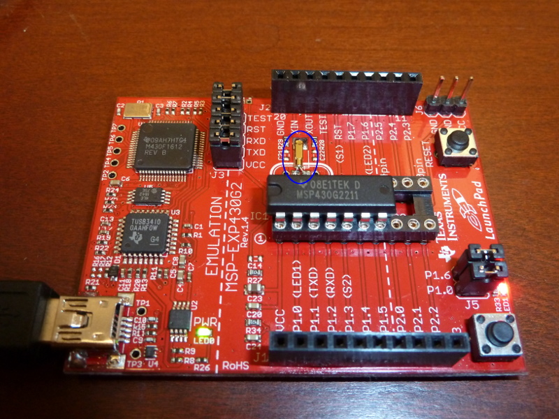
With the crystal, we can revise our hello program:
#include <msp430g2211.h>

#define RED_LED BIT0

unsigned int wdtCounter = 0;

void main(void)
{
    /* Set watchdog timer interval to 1000ms (requires external crystal to work) */
    WDTCTL = WDT_ADLY_1000;

    /* "Interrupt enable 1" for the Watchdog Timer interrupt */
    IE1 |= WDTIE;

    /* Set the LED pin as an output pin */
    P1DIR |= RED_LED;

    /* Turn on LED pin */
    P1OUT |= RED_LED;

    /* Go into low power mode 3, general interrupts enabled */
    __bis_SR_register( LPM3_bits + GIE );

    /* Do nothing...forever */
    for( ; ; ) { }
}

/* Watchdog Timer interrupt service routine.  The function prototype
 *  * tells the compiler that this will service the Watchdog Timer, and
 *   * then the function follows.
 *    */
void watchdog_timer(void) __attribute__((interrupt(WDT_VECTOR)));
void watchdog_timer(void)
{
    wdtCounter++;

    /* Count 1 interrupts x 1000ms = 1000ms, or one second */
    if(wdtCounter == 1) {
        /* Blink the LED pin */
        P1OUT ^= RED_LED;

        /* Reset the counter for the next blink */
        wdtCounter = 0;
    }
}
9. Blinking lights revisited
9.1. Using internal timer
We have everything we need now to do a good job with the "blinking lights" demo above, using interrupts to drive the entire program. This code uses the internal timer, so there is no need for an external crystal.
#include <msp430g2211.h>

#define RED_LED BIT0
#define GRN_LED BIT6
#define BUTTON  BIT3

int blink_mode = 0;        // which mode we start in
int blink_mask = RED_LED;  // which lights we blink
int wdtCounter = 0;

int main(void) {
    /* Set watchdog timer interval to 32ms */
    WDTCTL = WDT_MDLY_32;

    /* enable interrupts for the watchdog timer */
    IE1 |= WDTIE;

    /* Enable interrupts for our button */
    P1IE |= BUTTON;

    /* Clear our BUTTON in the Port 1 interrupt flag. */
    P1IFG &= ~BUTTON;

    /* Configure LED pins on port 1 as output pins */
    P1DIR |= RED_LED + GRN_LED;

    /* make sure green is turned off */
    P1OUT &= ~GRN_LED;

    /* go to sleep, low power mode 0 */
    __bis_SR_register( LPM0_bits + GIE );

    /* infinite loop */
    for( ; ; ) { }
}

/* Port 1 interrupt service routine.  This is for handling
 * our button presses.  First, this prototype tells
 * the compiler that the function handles interrupts for
 * Port 1.  Then the function follows.
 */
void Port_1(void) __attribute__((interrupt(PORT1_VECTOR)));
void Port_1(void)
{
    /* Clear the interrupt flag */
    P1IFG &= ~BUTTON; // P1.3 IFG cleared

    /* Switch blink modes */
    blink_mode = (blink_mode+1)%4;

    switch( blink_mode ) {
        case 0: /* blink red only - green off */
            blink_mask = RED_LED;
            P1OUT &= ~GRN_LED;
            break;
        case 1: /* blink green only - red off */
            blink_mask = GRN_LED;
            P1OUT &= ~RED_LED;
            break;
        case 2: /* blink red and green alternately */
            blink_mask = GRN_LED + RED_LED;
            P1OUT |= RED_LED;
            P1OUT &= ~GRN_LED;
            break;
        case 3: /* blink red and green together */
            blink_mask = GRN_LED + RED_LED;
            P1OUT |= RED_LED + GRN_LED;
            break;
    }
}

/* Watchdog Timer interrupt service routine.  The function prototype
 * tells the compiler that this will service the Watchdog Timer, and
 * then the function follows.
 */
void watchdog_timer(void) __attribute__((interrupt(WDT_VECTOR)));
void watchdog_timer(void)
{
    wdtCounter++;

    /* Count 10 interrupts x 32ms = 320ms, about 1/3 second */
    if(wdtCounter == 10) {
        /* Reset the counter for the next blink */
        wdtCounter = 0;

        /* blink the LEDs */
        P1OUT ^= blink_mask;
    }
}
9.2. Using external crystal
If we adapt the code for the external crystal, we can use the more-efficient low power mode 3.
#include <msp430g2211.h>

#define RED_LED BIT0
#define GRN_LED BIT6
#define BUTTON  BIT3

int blink_mode = 0;        // which mode we start in
int blink_mask = RED_LED;  // which lights we blink
int wdtCounter = 0;

int main(void) {
    /* Set watchdog timer interval to 16ms, won't work without external crystal */
    WDTCTL = WDT_ADLY_16;

    /* enable interrupts for the watchdog timer */
    IE1 |= WDTIE;

    /* Enable interrupts for our button */
    P1IE |= BUTTON;

    /* Clear our BUTTON in the Port 1 interrupt flag. */
    P1IFG &= ~BUTTON;

    /* Configure LED pins on port 1 as output pins */
    P1DIR |= RED_LED + GRN_LED;

    /* make sure green is turned off */
    P1OUT &= ~GRN_LED;

    /* go to sleep, low power mode 0 */
    __bis_SR_register( LPM3_bits + GIE );

    /* infinite loop */
    for( ; ; ) { }
}

/* Port 1 interrupt service routine.  This is for handling
 * our button presses.  First, this prototype tells
 * the compiler that the function handles interrupts for
 * Port 1.  Then the function follows.
 */
void Port_1(void) __attribute__((interrupt(PORT1_VECTOR)));
void Port_1(void)
{
    /* Clear the interrupt flag */
    P1IFG &= ~BUTTON; // P1.3 IFG cleared

    /* Switch blink modes */
    blink_mode = (blink_mode+1)%4;

    switch( blink_mode ) {
        case 0: /* blink red only - green off */
            blink_mask = RED_LED;
            P1OUT &= ~GRN_LED;
            break;
        case 1: /* blink green only - red off */
            blink_mask = GRN_LED;
            P1OUT &= ~RED_LED;
            break;
        case 2: /* blink red and green alternately */
            blink_mask = GRN_LED + RED_LED;
            P1OUT |= RED_LED;
            P1OUT &= ~GRN_LED;
            break;
        case 3: /* blink red and green together */
            blink_mask = GRN_LED + RED_LED;
            P1OUT |= RED_LED + GRN_LED;
            break;
    }
}

/* Watchdog Timer interrupt service routine.  The function prototype
 * tells the compiler that this will service the Watchdog Timer, and
 * then the function follows.
 */
void watchdog_timer(void) __attribute__((interrupt(WDT_VECTOR)));
void watchdog_timer(void)
{
    wdtCounter++;

    /* Count 20 interrupts x 16ms = 320ms, about 1/3 second */
    if(wdtCounter == 20) {
        /* Reset the counter for the next blink */
        wdtCounter = 0;

        /* blink the LEDs */
        P1OUT ^= blink_mask;
    }
}
10. Pulse Width Modulation
10.1. Sleeping LED
I’ve been wanting a good PWM example for a while now. There seems to be a lot to understand in order to set this up well, but I eventually managed to slap together a "sleeping" green LED program.
#include "msp430g2211.h"

#define GRN_LED BIT6

int pwmDirection = 1;

void main(void)
{
    /* Set watchdog timer interval to 32ms, internal timer */
    WDTCTL = WDT_MDLY_32;

    /* enable interrupts for the watchdog timer */
    IE1 |= WDTIE;

    /* Set green LED for ouput and then to pulse width modulation */
    P1DIR |= GRN_LED;
    P1SEL |= GRN_LED;

    /* The count that determines the PWM period */
    CCR0 = 1000-1;

    /* CCR1 is the PWM duty cycle, i.e. how much of the cycle is on vs. off */
    CCR1 = 1;

    /* CCR1 reset/set -- high voltage below count and low voltage when past */
    CCTL1 = OUTMOD_7;

    /* Timer A control set to submain clock TASSEL_2 and count up mode MC_1 */
    TACTL = TASSEL_2 + MC_1;

    /* go to sleep, low power mode 0 */
    __bis_SR_register(LPM0_bits + GIE);

    /* infinite loop */
    for( ; ; ) { }
}

/* Watchdog Timer interrupt service routine.  The function prototype
 * tells the compiler that this will service the Watchdog Timer, and
 * then the function follows.
 */
void watchdog_timer(void) __attribute__((interrupt(WDT_VECTOR)));
void watchdog_timer(void)
{
    CCR1 += pwmDirection*20;

    if( CCR1 > 980 || CCR1 < 20 ) pwmDirection = -pwmDirection;
}
There’s really a lot to understand here. The beginning is familiar; I set up the watchdog timer to generate interrupts. That’s because I’m using the interrupt service routine to change the brightness of my green LED, sequentially raising the brightness and then lowering it.
By the way, I used the green LED because the red LED apparently doesn’t do pulse width modulation. I’m not sure yet what it does do when you set its bit to 1 in the P1SEL variable. Green works, so we use green.
The key to understanding how PWM works is to know that it uses a counter and a comparison value. The values CCR0 and CCR1 set this up. CCR0 sets the bounds for the counter. In our program, it counts from 0 to 999. CCR1 sets the comparison value, which is initially 1, though we change it later in the watchdog_timer() function.
CCTL1 can be set to different values, depending on how you want your pulses to look. The header file give a rundown of the values:
#define OUTMOD_0            (0*0x20)  /* PWM output mode: 0 - output only */
#define OUTMOD_1            (1*0x20)  /* PWM output mode: 1 - set */
#define OUTMOD_2            (2*0x20)  /* PWM output mode: 2 - PWM toggle/reset */
#define OUTMOD_3            (3*0x20)  /* PWM output mode: 3 - PWM set/reset */
#define OUTMOD_4            (4*0x20)  /* PWM output mode: 4 - toggle */
#define OUTMOD_5            (5*0x20)  /* PWM output mode: 5 - Reset */
#define OUTMOD_6            (6*0x20)  /* PWM output mode: 6 - PWM toggle/set */
#define OUTMOD_7            (7*0x20)  /* PWM output mode: 7 - PWM reset/set */
We’ve used mode 7, which appears to set the pin high when the count is less than CCR1 and set it low when the counter passes CCR1. Notice that when the program starts, the LED is dark, then it gets brighter as CCR1 increases. If we’d used mode 3, it would have done the opposite: start bright and go dim.
Finally, we set values for Timer A via TACTL (apparently this is the timer that does pulse width modulation). We set it to use the submain timer (which runs at 1mhz) via TASSEL_2 and "count up" mode with MC_1.
Other possibilities are given in the header file, and it is worth perusing. For example, we could have used TASSEL_1 to select the external timer crystal to run the counter (if you’ve soldered yours to your Launchpad). The crystal runs at only 32.678 kHz, though, so we’d probably want to count to a value less than 999 in CCR0 (and scale everything else accordingly) or we might notice flicker.
10.2. Which pins do PWM?
I didn’t know which pins can do pulse width modulation, so I decided to modify the sleeping LED program to run all the pins (or at least I used a bitmask for all of the pins). Then I hooked up my multimeter to see which pins changed in time with the green LED.
It appears that on the msp430g2211, the only pins that do PWM are pin 1.2 and pin 1.6. Here’s the code I used; check for yourself.
#include "msp430g2211.h"

int pwmDirection = 1;
int wdtCounter = 0;

void main(void)
{
    /* Set watchdog timer interval to 32ms, internal timer */
    WDTCTL = WDT_MDLY_32;

    /* enable interrupts for the watchdog timer */
    IE1 |= WDTIE;

    /* Set all pins for output and PWM (although not all can do it) */
    P1DIR |= 0xFF;
    P1SEL |= 0xFF;

    /* The count that determines the PWM period */
    CCR0 = 1000-1;

    /* CCR1 is the PWM duty cycle, i.e. how much of the cycle is on vs. off */
    CCR1 = 1;

    /* CCR1 reset/set -- reset pin when below count and set above? */
    CCTL1 = OUTMOD_7;

    /* Timer A control set to submain clock TASSEL_2 and count up mode MC_1 */
    TACTL = TASSEL_2 + MC_1;

    /* go to sleep, low power mode 0 */
    __bis_SR_register(LPM0_bits + GIE);

    /* infinite loop */
    for( ; ; ) { }
}

/* Watchdog Timer interrupt service routine.  The function prototype
 * tells the compiler that this will service the Watchdog Timer, and
 * then the function follows.
 */
void watchdog_timer(void) __attribute__((interrupt(WDT_VECTOR)));
void watchdog_timer(void)
{
    wdtCounter++;

    /* We'll change every 2 interrupts to slow things a bit, so we have
     * time to watch on the multimeter.
     */
    if( wdtCounter >= 2 ) {
        wdtCounter = 0;

        CCR1 += pwmDirection*20;

        if( CCR1 > 980 || CCR1 < 20 ) pwmDirection = -pwmDirection;
    }
}
11. Talking to MSP430 via Launchpad USB interface
It is really, really tricky getting Linux to talk to the Launchpad via the USB interface under Linux. I was able to do it, but it requires executing these steps in exactly the right order.
Step 1: Unplug the USB cable for the Launchpad and reinsert it.
Step 2: Run the command mspdebug rf2500 exit
Step 3: Run the command stty 2400 -F /dev/ttyACM0
If this command executes successfully, you are basically home free. But don’t get excited and mess up the order of the next two steps!
Step 4: Execute the command cat /dev/ttyACM0
Step 5: If you are running the TI demo program with the temperature readings (the one that lights up the red LED when the temperature rises and the green LED when the temperature cools), press switch 2 to start the program. If the temperature of your room is at least 65°F, you should start seeing capital letters on your screen. (65 is the byte value of capital A, 66 is capital B, and so on).
|
|
If you do these steps out of order, you may get an error like /dev/ttyACM0: Input/output error or cat: /dev/ttyACM0: Input/output error. Do them in order. |
Alternate steps that work if you are using a terminal program like putty or minicom.
Step 1: Unplug the USB cable for the Launchpad and reinsert it.
Step 2: Run the command mspdebug rf2500 exit
Step 3a: (For putty) Run putty, set it for serial, and connect to /dev/ttyACM0 at speed 2400.
Step 3b: (For minicom) Run minicom -b 2400 -D /dev/ttyACM0
Step 4: Press switch 2 on the Launchpad to start reporting temperatures.
|
|
I’d suggest giving all of the commands on a single line. That will help make sure you can’t do anything in the wrong order. For example, it is much harder to get things wrong if you type: mspdebug rf2500 exit; stty 2400 -F /dev/ttyACM0; echo 'Go!'; cat /dev/ttyACM0 |
12. Yet another Hello World
Perhaps it’s silly to write yet another Hello World for the MSP 430, but I was perusing some of the TI demo code for the temperature demo, and I learned some new timer tricks. The significant new thing is a way to use Low Power Mode 3 and still trigger timer interrupts; but this method doesn’t require an external clock crystal.
The trick is to use Timer A to trigger interrupts based on counting (much like setting up pulse width modulation) running off from the auxilliary clock ACLK, but to first redefine ACLK to use the chip’s internal Very Low-power Oscillator (LFXT1S_2) rather than the external crystal oscillator (LFXT1S_0).
One extra touch in this program is the use of a clock divider on the auxilliary clock with DIVA_1 (we divide the 12kHz clock by two to create a 6kHz clock). We could have used other values like DIVA_0 to use the full clock speed, if we also changed the counter value from 5999 to 11999 correspondingly.
We could also have used DIVA_2 for a /4 divider (if we counted to 2999) or DIVA_3 for a /8 divider (if we counted to 1499). All would have given the same "1 second on 1 second off" blink time.
|
|
There’s also the possibility of using further clock dividers when setting up TACTL but this code didn’t do that. Check the header file about ID_0 through ID_3, and remember that you’ll want to change the counter value accordingly. |
#include <msp430g2211.h>

#define RED_LED BIT0

unsigned int wdtCounter = 0;

void main(void)
{
    /* Set the LED pin as an output pin and turn it on*/
    P1DIR |= RED_LED;
    P1OUT |= RED_LED;

    /* The basic clock system control register 3 controls the oscillator
     * the auxilliary clock uses.  Change ACLK from external timer crystal
     * oscillator to internal very low-power oscillator (VLO) clock,
     * which runs at appoximately 12kHz.
     */
    BCSCTL3 |= LFXT1S_2;

    /* Basic clock system control register 1 controls the auxilliary clock
     * divider.  Set ACLK to use Divider 1, i.e. divided by 2^1. */
    BCSCTL1 |= DIVA_1;

    /* Set TimerA to use auxilliary clock TASSEL_1 and count up mode MC_1 */
    TACTL = TASSEL_1 + MC_1;

    /* Set counter period 5999+1 = 1 second */
    TACCR0 = 5999;

    /* Set capture/compare mode interrupts enabled, to trigger an interrupt
     * when TACCR0 (5999) is reached. */
    TACCTL0 = CCIE;

    /* Go into low power mode 3, general interrupts enabled */
    __bis_SR_register( LPM3_bits + GIE );

    /* Do nothing...forever */
    for( ; ; ) { }
}

/* Timer A interrupt service routine.  The function prototype
 * tells the compiler that this will service the Timer A0 interrupt,
 * and then the function follows.
 */
void Timer_A_isr(void) __attribute__((interrupt(TIMERA0_VECTOR)));
void Timer_A_isr(void)
{
    /* Blink the LED pin */
    P1OUT ^= RED_LED;

    /* clear interrupt flag */
    TACCTL0 &= ~CCIFG;
}
13. Serial communication 1
Some of the MSP430 chips have built-in serial communication capabilities, but all of the chips should be able to communicate serial via a method called "bit banging." Bit banging is a technique of using the clock to raise and lower a pin for the correct durations to send a message.
This code also blinks the LEDs when transmitting, the red led when sending a 1 and the green led when sending a 0. You’ll notice after transmission, that the red light stays lit (because the serial line is left high).
To communicate one byte a 0 is sent (called the start bit), then the bits of the byte (in reverse order), then a 1 (called the stop bit). If you set your computer’s serial line to the correct speed, as detailed above [Talking_to_MSP430], you should be able to see the message on screen.
|
|
About the "Ticks per bit" values… You might notice that the math suggests a value of 13 for 9600 bps, since 125000/9600 = 13.02. I found that 13 did not work for me, but 12 was fine. I also played with the 2400 bps value as well as the 1200 bps value. In general, I found that I could lower the constants a few places (effectively making the communication faster) without breaking things. |
#include <msp430g2211.h>

/* Demo UART application.  After you press the button, this transmits
 * a "Hello, world!" string to the computer at 2400 bps.
 */

#define   RED_LED   BIT0
#define   GRN_LED   BIT6

#define   BUTTON    BIT3

#define   TXD       BIT1
#define   RXD       BIT2

/* Ticks per bit.  Use the following values based on speed:
 * 9600 bps ->  12
 * 2400 bps ->  52
 * 1200 bps -> 104
 * I did not have success with slower speeds, like 300 bps.
 */
#define   TPB      52

int TXWord;
unsigned char bitcnt = 0;

/* function prototypes */
void initUart( void );
void sendByte( unsigned char b );
void sendString( const char *str );

void main(void) {
    /* stop the watchdog timer */
    WDTCTL = WDTPW + WDTHOLD;

    /* LEDs off, but later we'll blink them as we send bits */
    P1DIR |= RED_LED+GRN_LED;
    P1OUT &= ~ (RED_LED + GRN_LED );

    initUart();

    /* We'll use the button to let the chip know we're ready to communicate.
     * Direction is receive, clear interrupt flag, and
     * interrupts are enabled.
     */
    P1DIR &= ~BUTTON;
    P1IFG &= ~BUTTON;
    P1IE |= BUTTON;

    for( ; ; ) {
        /* go to sleep until button press */
        __bis_SR_register( LPM3_bits + GIE );
        sendString( "Hello, world!\r\n" );
    }
}

void initUart( void ) {
    /* Set up transmit as output pin and set it high */
    P1OUT |= TXD;
    P1DIR |= TXD;

    /* set up the clocks for 1 Mhz */
    BCSCTL1 = CALBC1_1MHZ;
    DCOCTL = CALDCO_1MHZ;
    BCSCTL2 &= ~(DIVS_3);

    /* Set timer A to use count up mode 4 Mhz / 8 = 500 Khz. */
    TACTL = TASSEL_2 + MC_1 + ID_3 + TACLR;

    /* Set ticks-per-bit to specify communication speed */
    TACCR0 = TPB;
}

void sendByte( unsigned char b ) {
    /* load the byte */
    TXWord = b;
    /* add stop bit */
    TXWord |= 0x100;
    /* add start bit */
    TXWord <<= 1;

    /* 1 start bit + 8 data bits + 1 stop bit */
    bitcnt = 10;

    /* clear the counter, clear interrupt flag, and tell Timer A0 to
     * start triggering interrupts
     */
    TACTL |= TACLR;
    TACCTL0 &= ~CCIFG;
    TACCTL0 |= CCIE;

    /* sleep until message sent */
    while( TACCTL0 & CCIE ) {
        __bis_SR_register( LPM0_bits + GIE );
    }
}

/* Sends a string of characters to the computer */
void sendString( const char *str ) {
    char *c = str;

    for( ; *c ; c++ ) {
        sendByte( *c );
    }
}


/* This continuously sends bits of the TXWord starting from the
 * least significant bit (the 0 start bit).  One bit is sent every
 * time the handler is activated.
 */
void TimerA0 (void) __attribute__((interrupt(TIMERA0_VECTOR)));
void TimerA0(void) {
    TACCTL0 &= ~CCIFG;

    if( ! bitcnt ) {
        /* no bits left, turn off interrupts and wake up */
        TACCTL0 &= ~ CCIE;
        __bic_SR_register_on_exit( LPM0_bits );
        return;
    } else {
        /* send least significant bit */
        if( TXWord & 0x01 ) {
            P1OUT |= TXD;
            P1OUT |= RED_LED;           // for testing
            P1OUT &= ~ GRN_LED;         // for testing
        } else {
            P1OUT &= ~TXD;
            P1OUT |= GRN_LED;           // for testing
            P1OUT &= ~ RED_LED;         // for testing
        }

        /* shift word to remove one bit */
        TXWord >>= 1;
        bitcnt --;
    }
}

/* A button press triggers this interrupt, which wakes
 * up the main program to send a message.
 */
void Port_1 (void) __attribute__((interrupt(PORT1_VECTOR)));
void Port_1(void) {
    P1IFG &= ~BUTTON;

    /* wake up the main program */
     __bic_SR_register_on_exit( LPM3_bits );
}
14. Serial communication 2
It seemed to me that our last serial communication program left a bit of empty time between consecutive bytes in a transmission, after the last stop bit is transmitted but before the next start bit goes out. If there is a whole block of data, it would be better if the next byte were just loaded and the communication continued. The next program does precisely that.
|
|
I have now changed the comments for the "Ticks per bit" for 9600 bps back to 13. By testing, I discovered that the previous program could be made reliable with a value 13 if I used a small delay to shorten the start bit. I think the setting of 12 accomplished something of the same result. In this program, there’s a bit of setup code that runs during that first interrupt, and it seems to provide adequate delay to make communication reliable. |
#include <msp430g2211.h>
#include <string.h>

/* Demo UART application.  After you press the button, this transmits
 * a "Hello, world!" string to the computer at 2400 bps.
 */

#define   RED_LED   BIT0
#define   GRN_LED   BIT6

#define   BUTTON    BIT3

#define   TXD       BIT1
#define   RXD       BIT2

/* Ticks per bit.  Use the following values based on speed:
 * 9600 bps ->  13
 * 2400 bps ->  52
 * 1200 bps -> 104
 * I did not have success with slower speeds, like 300 bps.
 */
#define   TPB      52

/* A pointer to the data to send, and a counter of the bytes. */
unsigned char *data;
unsigned int bytestosend = 0;

/* The actual byte we are transmitting, with its start and stop bits,
 * and a counter of the bits left to send.
 */
int TXWord;
unsigned char bitcnt = 0;

/* function prototypes */
void initUart( void );
int sendByte( unsigned char b );
int sendBytes( const unsigned char *d, int len );
int sendString( const char *str );

void main(void) {
    /* stop the watchdog timer */
    WDTCTL = WDTPW + WDTHOLD;

    /* LEDs off, but later we'll blink them as we send bits */
    P1DIR |= RED_LED+GRN_LED;
    P1OUT &= ~ (RED_LED + GRN_LED );

    initUart();

    /* We'll use the button to let the chip know we're ready to communicate.
     * Direction is receive, clear interrupt flag, and
     * interrupts are enabled.
     */
    P1DIR &= ~BUTTON;
    P1IFG &= ~BUTTON;
    P1IE |= BUTTON;

    for( ; ; ) {
        /* go to sleep until button press */
        __bis_SR_register( LPM3_bits + GIE );
        sendString( "Hello, world!\r\n" );
    }
}

void initUart( void ) {
    /* Set up transmit as output pin and set it high */
    P1OUT |= TXD;
    P1DIR |= TXD;

    /* set up the clocks for 1 mhz */
    BCSCTL1 = CALBC1_1MHZ;
    DCOCTL = CALDCO_1MHZ;
    BCSCTL2 &= ~(DIVS_3);

    /* Set timer A to use count up mode 1 mhz / 8 = 125 khz. */
    TACTL = TASSEL_2 + MC_1 + ID_3 + TACLR;

    /* Set ticks-per-bit to specify communication speed */
    TACCR0 = TPB;
}

/* Prepares a block of data to be sent. Returns number of bytes sent. */
int sendBytes( const unsigned char *d, int len ) {
    /* can't queue up data if we're still sending */
    if( bytestosend > 0 ) return 0;

    bitcnt = 0;
    data = d;
    bytestosend = len;

    /* clear interrupt flag, and tell Timer A0 to
     * start triggering interrupts
     */
    TACCTL0 &= ~CCIFG;
    TACCTL0 |= CCIE;

    /* sleep until message sent */
    while( TACCTL0 & CCIE ) {
        __bis_SR_register( LPM0_bits + GIE );
    }

    return len;
}

/* Sends a single byte to the computer.  Returns number of bytes sent. */
int sendByte( unsigned char b ) {
    return sendBytes( &b, 1 );
}

/* Sends a string to the computer.  Returns number of bytes sent. */
int sendString( const char *str ) {
    return sendBytes( str, strlen(str) );
}

/* This continuously sends bits of the TXWord starting from the
 * least significant bit (the 0 start bit).  One bit is sent every
 * time the handler is activated.  When the bits run out, a new
 * byte is loaded from the data pointer, until bytestosend equals 0.
 */
void TimerA0 (void) __attribute__((interrupt(TIMERA0_VECTOR)));
void TimerA0(void) {
    TACCTL0 &= ~CCIFG;

    /* if no bits to send, either load a byte or return */
    if( ! bitcnt ) {
        if( bytestosend > 0 ) {
            /* load the byte */
            TXWord = *data++;
            /* add stop bit */
            TXWord |= 0x100;
            /* add start bit */
            TXWord <<= 1;

            /* 1 start bit + 8 data bits + 1 stop bit */
            bitcnt = 10;

            bytestosend --;
        } else {
            /* no bits left, turn off interrupts and wake up */
            TACCTL0 &= ~ CCIE;
            __bic_SR_register_on_exit( LPM0_bits );
            return;
        }
    }

    /* send least significant bit */
    if( TXWord & 0x01 ) {
        P1OUT |= TXD;
        P1OUT |= RED_LED;               // for testing
        P1OUT &= ~ GRN_LED;             // for testing
    } else {
        P1OUT &= ~TXD;
        P1OUT |= GRN_LED;               // for testing
        P1OUT &= ~ RED_LED;             // for testing
    }

    /* shift word to remove one bit */
    TXWord >>= 1;
    bitcnt --;
}

/* A button press triggers this interrupt, which wakes
 * up the main program to send a message.
 */
void Port_1 (void) __attribute__((interrupt(PORT1_VECTOR)));
void Port_1(void) {
    P1IFG &= ~BUTTON;

    /* wake up the main program */
     __bic_SR_register_on_exit( LPM3_bits );
}
You may wonder that we didn’t just call sendString() directly from the Port_1() interrupt handler in either this program or the previous one. The reason we didn’t do that is that sendBytes() sleeps until the data has been sent. In general, interrupts are disabled while in an interrupt handler. If we go to sleep while in the button handler, there’s no convenient way for the TimerA0() to trigger and clear the data out.
It is possible to adjust the program so that we can call sendString() directly from the Port_1() handler. We’d need to make these changes.
-
Sleep in LPM0 instead of LPM3 in the
main()function, since Timer A0 can’t trigger in LPM3. -
Remove the while loop and sleep code from
sendBytes()so it returns right away. -
Remove the
__bic_SR_register_on_exit()call fromPort_1()and replace it with a call tosendString().
15. Adding button debounce
If you tried the previous two serial communication programs, you may notice that on occasion you got more than one "Hello, world!" when you pressed Switch 2. That is probably due to something called button bounce. When you switch a physical button, it doesn’t always go cleanly from high voltage to low voltage (or vice versa). There is often a short period where the voltage oscillates back and forth before settling. These bounces can trigger extra button interrupts and repeated messages.
Button debouncing can be handled in hardware or software. In software, we basically handle button bounce by ignoring new interrupts for a short period of time after the initial interrupt. In the next program, I’ve configured the Watchdog timer to use the very low-power oscillator (VLO), and used that to debounce the button.
Most of the changes occur in the Port_1() handler, which now disables the button interrupt and enables the Watchdog timer; and in the new WDT_ISR(), which catches a Watchdog timer interrupt to re-enable the button. Don’t overlook in the main program, however, where we set the oscillator by modifying BCSCTL3.
#include <msp430g2211.h>
#include <string.h>

/* Demo UART application.  After you press the button, this transmits
 * a "Hello, world!" string to the computer at 2400 bps.
 */

#define   RED_LED   BIT0
#define   GRN_LED   BIT6

#define   BUTTON    BIT3

#define   TXD       BIT1
#define   RXD       BIT2

/* Ticks per bit.  Use the following values based on speed:
 * 9600 bps ->  13
 * 2400 bps ->  52
 * 1200 bps -> 104
 * I did not have success with slower speeds, like 300 bps.
 */
#define   TPB      52

/* A pointer to the data to send, and a counter of the bytes. */
unsigned char *data;
unsigned int bytestosend = 0;

/* The actual byte we are transmitting, with its start and stop bits,
 * and a counter of the bits left to send.
 */
int TXWord;
unsigned char bitcnt = 0;

/* function prototypes */
void initUart( void );
int sendByte( unsigned char b );
int sendBytes( const unsigned char *d, int len );
int sendString( const char *str );

void main(void) {
    /* stop the watchdog timer */
    WDTCTL = WDTPW + WDTHOLD;

    /* For debouncing: set the auxilliary clock to use very low-power
     * oscillator.  Later, we'll have the Watchdog timer use the
     * auxilliary clock for debouncing the button.
     */
    BCSCTL3 |= LFXT1S_2;

    /* LEDs off, but later we'll blink them as we send bits */
    P1DIR |= RED_LED+GRN_LED;
    P1OUT &= ~ (RED_LED + GRN_LED );

    initUart();

    /* We'll use the button to let the chip know we're ready to communicate.
     * Direction is receive, clear interrupt flag, and
     * interrupts are enabled.
     */
    P1DIR &= ~BUTTON;
    P1IFG &= ~BUTTON;
    P1IE |= BUTTON;

    for( ; ; ) {
        /* go to sleep until button press */
        __bis_SR_register( LPM3_bits + GIE );
        sendString( "Hello, world!\r\n" );
    }
}

void initUart( void ) {
    /* Set up transmit as output pin and set it high */
    P1OUT |= TXD;
    P1DIR |= TXD;

    /* set up the clocks for 1 mhz */
    BCSCTL1 = CALBC1_1MHZ;
    DCOCTL = CALDCO_1MHZ;
    BCSCTL2 &= ~(DIVS_3);

    /* Set timer A to use count up mode 1 mhz / 8 = 125 khz. */
    TACTL = TASSEL_2 + MC_1 + ID_3 + TACLR;

    /* Set ticks-per-bit to specify communication speed */
    TACCR0 = TPB;
}

/* Prepares a block of data to be sent. Returns number of bytes sent. */
int sendBytes( const unsigned char *d, int len ) {
    /* can't queue up data if we're still sending */
    if( bytestosend > 0 ) return 0;

    bitcnt = 0;
    data = d;
    bytestosend = len;

    /* clear interrupt flag, and tell Timer A0 to
     * start triggering interrupts
     */
    TACCTL0 &= ~CCIFG;
    TACCTL0 |= CCIE;

    /* sleep until message sent */
    while( TACCTL0 & CCIE ) {
        __bis_SR_register( LPM0_bits + GIE );
    }

    return len;
}

/* Sends a single byte to the computer.  Returns number of bytes sent. */
int sendByte( unsigned char b ) {
    return sendBytes( &b, 1 );
}

/* Sends a string to the computer.  Returns number of bytes sent. */
int sendString( const char *str ) {
    return sendBytes( str, strlen(str) );
}

/* This continuously sends bits of the TXWord starting from the
 * least significant bit (the 0 start bit).  One bit is sent every
 * time the handler is activated.  When the bits run out, a new
 * byte is loaded from the data pointer, until bytestosend equals 0.
 */
void TimerA0 (void) __attribute__((interrupt(TIMERA0_VECTOR)));
void TimerA0(void) {
    TACCTL0 &= ~CCIFG;

    /* if no bits to send, either load a byte or return */
    if( ! bitcnt ) {
        if( bytestosend > 0 ) {
            /* load the byte */
            TXWord = *data++;
            /* add stop bit */
            TXWord |= 0x100;
            /* add start bit */
            TXWord <<= 1;

            /* 1 start bit + 8 data bits + 1 stop bit */
            bitcnt = 10;

            bytestosend --;
        } else {
            /* no bits left, turn off interrupts and wake up */
            TACCTL0 &= ~ CCIE;
            __bic_SR_register_on_exit( LPM0_bits );
            return;
        }
    }

    /* send least significant bit */
    if( TXWord & 0x01 ) {
        P1OUT |= TXD;
        P1OUT |= RED_LED;               // for testing
        P1OUT &= ~ GRN_LED;             // for testing
    } else {
        P1OUT &= ~TXD;
        P1OUT |= GRN_LED;               // for testing
        P1OUT &= ~ RED_LED;             // for testing
    }

    /* shift word to remove one bit */
    TXWord >>= 1;
    bitcnt --;
}

/* A button press triggers this interrupt, which wakes
 * up the main program to send a message.
 */
void Port_1 (void) __attribute__((interrupt(PORT1_VECTOR)));
void Port_1(void) {
    /* disable interrupts for the button to handle button bounce */
    P1IE &= ~BUTTON;
    /* clear the interrupt flag for button */
    P1IFG &= ~BUTTON;

    /* set watchdog timer to trigger every 16*32.768k/12k = 44 ms */
    WDTCTL = WDT_ADLY_16;
    /* clear watchdog timer interrupt flag */
    IFG1 &= ~WDTIFG;
    /* enable watchdog timer interrupts; in 44 ms the button
     * will be re-enabled by WDT_ISR() -- program will continue in
     * the meantime.
     */
    IE1 |= WDTIE;

    /* wake up the main program */
     __bic_SR_register_on_exit( LPM3_bits );
}

/* This function catches watchdog timer interrupts, which are
 * set to happen 44ms after the user presses the button.  The
 * button has had time to "bounce" and we can turn the button
 * interrupts back on.
 */
void WDT_ISR(void) __attribute__((interrupt(WDT_VECTOR)));
void WDT_ISR(void)
{
    /* Disable interrupts on the watchdog timer */
    IE1 &= ~WDTIE;
    /* clear the interrupt flag for watchdog timer */
    IFG1 &= ~WDTIFG;
    /* resume holding the watchdog timer so it doesn't reset the chip */
    WDTCTL = WDTPW + WDTHOLD;
    /* and re-enable interrupts for the button */
    P1IE |= BUTTON;
}|
|
Normally WDT_ADLY_16 triggers interrupts every 16 milliseconds, but this value assumes you are using the 32.768k external crystal oscillator. Since we set the auxiallary clock to use the internal very low-power oscillator, which runs at a slower 12k rate, we get interrupts every 16*32.768k/12k = 43.7 ms. This should be long enough to debounce the button, but we could have added a counter to WDT_ISR() or set a clock divider by modifying BCSCTL1 (as in [Yet_another_hello]) if we needed longer delays. |
|
|
Since I wrote this experiment, it occurs to me that it is only half done. I had a button that would bounce when pressed (and this addresses it). But many buttons bounce when pressed and when released. We shouldn’t wake the program up in Port_1() but rather in WDT_ISR() if we check and the button is still down. |
16. A Uart receiver
I can’t believe how much time I spent getting the next application to work. I finally realize something about all of the TI demo code. If you use mspgcc4 for your projects, then this is really important. So I’m going to make a big warning sign here:
|
|
In TI code, interrupt handlers don’t clear the relevant interrupt flag. If you port this code to mspgcc4, you have to clear the interrupt flag in all of your interrupt handlers, or your code will not work! I assume the TI compiler must do this for you, and perhaps this is understood as part of what the #pragma directive does. |
You’ll see that I clear the interrupt flag as the first line of the TimerA1() interrupt handler.
The progam that follows is a simple Uart receiver. It talks to the computer through the Launchpad device. When you type characters on the computer (in a terminal program like minicom) the LEDs on the Launchpad blink. The red LED lights up for 1s, and the green LED lights up for 0s.
#include <msp430g2211.h>

/* Demo UART application.  Receives bytes from the computer
 * at 2400 bps, and blinks the red LED for 1s and the green
 * LED for 0s.
 */

#define   RED_LED   BIT0
#define   GRN_LED   BIT6

#define   RXD       BIT2

/* Ticks per bit, and ticks per half.  Use the following values based on speed:
 * 9600 bps ->  13
 * 2400 bps ->  52
 * 1200 bps -> 104
 * I did not have success with slower speeds, like 300 bps.
 */
#define   TPB      52
#define   TPH      (TPB - TPB/2)

int RXByte;
unsigned char bitcnt = 0;

/* function prototypes */
void initUart( void );
void RX_Ready( void );

void main(void) {
    /* stop the watchdog timer */
    WDTCTL = WDTPW + WDTHOLD;

    /* LEDs off, but we'll blink them as we send or receive bits */
    P1DIR |= RED_LED+GRN_LED;
    P1OUT &= ~ (RED_LED + GRN_LED );

    initUart();

    for( ; ; ) {
        RX_Ready();
        /* go to sleep and wait for data */
        __bis_SR_register( LPM0_bits + GIE );
    }
}

void initUart( void ) {
    /* set up the clocks for 1 mhz */
    BCSCTL1 = CALBC1_1MHZ;
    DCOCTL = CALDCO_1MHZ;
    BCSCTL2 &= ~(DIVS_3);

    /* Set timer A to use continuous mode 1 mhz / 8 = 125 khz. */
    TACTL = TASSEL_2 + MC_2 + ID_3;

    /* RXD set for timer function as a receive pin */
    P1SEL |= RXD;
    P1DIR &= ~ RXD;
}

void RX_Ready( void ) {
    /* Make ready to receive character.  Syncronize, negative edge
     * capture, enable interrupts.
     */
    bitcnt = 8;
    CCTL1 = SCS + OUTMOD0 + CM1 + CAP + CCIE;
}

void TimerA1 (void) __attribute__((interrupt(TIMERA1_VECTOR)));
void TimerA1(void) {
    /* reset the interrupt flag */
    CCTL1 &= ~CCIFG;

    /* add ticks per bit to trigger again on next bit in stream */
    CCR1 += TPB;

    /* If we just caught the 0 start bit, then turn off capture
     * mode (it'll be all compares from here forward) and add
     * tick-per-half so we'll catch signals in the middle of
     * each bit.
     */
    if( CCTL1 & CAP ) {
        CCTL1 &= ~ CAP;
        CCR1 += TPH;
    }
    /* Otherwise we need to catch another bit.  We'll shift right
     * the currently received data, and add new bits on the left.
     */
    else {
        RXByte >>= 1;

        if( CCTL1 & SCCI ) {
            RXByte |= 0x80;
            P1OUT |= RED_LED;           // for testing
            P1OUT &= ~ GRN_LED;         // for testing
        } else {
            P1OUT |= GRN_LED;           // for testing
            P1OUT &= ~ RED_LED;         // for testing
        }
        bitcnt --;

        if( ! bitcnt ) {
            /* Go back to capture mode and wait for next start bit */
            CCTL1 |= CAP;
            bitcnt = 8;
            P1OUT &= ~ (RED_LED + GRN_LED);     // for testing

            __bic_SR_register_on_exit( LPM0_bits );
        }
    }
}
To use this program, I give a command like this:
$ mspdebug rf2500 exit; minicom -o -b 2400 -D /dev/ttyACM0
...
17. Send and Receive
The next program sends and receives, and to some extent can do both simultaneously. If you look, you’ll notice that I’ve changed the transmitting code slightly to be more in line with demo code from TI. This asserts high and low (or mark and space as they are sometimes called) by modifying CCTL0 and setting or clearing OUTMOD2. The effect is essentially the same, though this seemed more reliable in some situations.
Although the program works, there is a timing problem with it. If you simply
type characters on the computer, you will not encounter the problem because you
can’t type fast enough. However, if the computer sends data to the Launchpad
too quickly, the program can still be executing while( !sendByte( &onebyte ))
; when the start bit of the next character arrives. If that happens, the next
characters will be garbled.
This can happen, for example, if the data is being sent by software instead of from the keyboard. You can also observe it if you use cut-and-paste to paste data into the terminal program like minicom. Minicom will be happy to transfer the pasted data faster than we can accept it on the Launchpad.
#include <msp430g2211.h>
/* Demo UART application. Receives bytes from the computer
* at 2400 bps, and sends the same character back to the computer.
*/
#define TXD BIT1
#define RXD BIT2
/* Ticks per bit, and ticks per half. Use the following values based on speed:
* 9600 bps -> 13
* 2400 bps -> 52
* 1200 bps -> 104
* I did not have success with slower speeds, like 300 bps.
*/
#define TPB 52
#define TPH (TPB - TPB/2)
unsigned int TXWord;
unsigned char RXByte;
unsigned char rxbitcnt = 0;
unsigned char txbitcnt = 0;
/* A pointer to the data to send, and a counter of the bytes. */
unsigned char *data;
unsigned char onebyte = 0;
unsigned int bytestosend = 0;
/* function prototypes */
void initUart( void );
void RX_Ready( void );
int sendByte( unsigned char *b ); // pointer to byte here!
int sendBytes( const unsigned char *d, int len );
int sendString( const char *str );
int sendFinished( void );
void main(void) {
/* stop the watchdog timer */
WDTCTL = WDTPW + WDTHOLD;
initUart();
for( ; ; ) {
RX_Ready();
/* go to sleep and wait for data */
__bis_SR_register( LPM0_bits + GIE );
/* store byte so we can send and receive at same time */
onebyte = RXByte;
/* loop until the byte is queued to send */
while( !sendByte( &onebyte ))
;
}
}
void initUart( void ) {
/* set up the clocks for 1 mhz */
BCSCTL1 = CALBC1_1MHZ;
DCOCTL = CALDCO_1MHZ;
BCSCTL2 &= ~(DIVS_3);
/* Set timer A to use continuous mode 1 mhz / 8 = 125 khz. */
TACTL = TASSEL_2 + MC_2 + ID_3;
/* When TXD isn't being used, it should be high */
CCTL0 = OUT;
/* TXD and RXD set for timer function, RXD input, TXD output */
P1SEL |= TXD + RXD;
P1DIR &= ~ RXD;
P1DIR |= TXD;
}
/* Prepares a block of data to be sent. Returns number of bytes sent. */
int sendBytes( const unsigned char *d, int len ) {
/* can't queue up data if we're still sending */
if( CCTL0 & CCIE ) return 0;
txbitcnt = 0;
data = d;
bytestosend = len;
CCR0 = TAR + TPB;
/* Timer A0 to start triggering interrupts */
CCTL0 = CCIS0 + OUTMOD0 + CCIE;
return len;
}
/* Sends a single byte to the computer. Returns number of bytes sent. */
int sendByte( unsigned char *b ) {
return sendBytes( b, 1 );
}
/* Sends a string to the computer. Returns number of bytes sent. */
int sendString( const char *str ) {
return sendBytes( str, strlen(str) );
}
/* Tests if a transmission is done */
int sendFinished( void ) {
return ( CCTL0 & CCIE ) == 0;
}
/* This continuously sends bits of the TXWord starting from the
* least significant bit (the 0 start bit). One bit is sent every
* time the handler is activated. When the bits run out, a new
* byte is loaded from the data pointer, until bytestosend equals 0.
*/
void TimerA0 (void) __attribute__((interrupt(TIMERA0_VECTOR)));
void TimerA0(void) {
/* reset the interrupt flag */
CCTL0 &= ~CCIFG;
/* add ticks per bit to trigger again on next bit in stream */
CCR0 += TPB;
/* if no bits to send, either load a byte or return */
if( ! txbitcnt ) {
if( bytestosend > 0 ) {
/* load the byte */
TXWord = *data++;
/* add stop bit */
TXWord |= 0x100;
/* add start bit */
TXWord <<= 1;
/* 1 start bit + 8 data bits + 1 stop bit */
txbitcnt = 10;
bytestosend --;
} else {
/* no bits left, turn off interrupts */
CCTL0 &= ~ CCIE;
return;
}
}
/* send least significant bit */
if( TXWord & 0x01 ) {
CCTL0 &= ~ OUTMOD2;
} else {
CCTL0 |= OUTMOD2;
}
/* shift word to remove one bit */
TXWord >>= 1;
txbitcnt --;
}
void RX_Ready( void ) {
/* Make ready to receive character. Syncronize, negative edge
* capture, enable interrupts.
*/
rxbitcnt = 8;
CCTL1 = SCS + OUTMOD0 + CM1 + CAP + CCIE;
}
void TimerA1 (void) __attribute__((interrupt(TIMERA1_VECTOR)));
void TimerA1(void) {
/* reset the interrupt flag */
CCTL1 &= ~CCIFG;
/* add ticks per bit to trigger again on next bit in stream */
CCR1 += TPB;
/* If we just caught the 0 start bit, then turn off capture
* mode (it'll be all compares from here forward) and add
* tick-per-half so we'll catch signals in the middle of
* each bit.
*/
if( CCTL1 & CAP ) {
CCTL1 &= ~ CAP;
CCR1 += TPH;
}
/* Otherwise we need to catch another bit. We'll shift right
* the currently received data, and add new bits on the left.
*/
else {
RXByte >>= 1;
if( CCTL1 & SCCI ) {
RXByte |= 0x80;
} else {
}
rxbitcnt --;
if( ! rxbitcnt ) {
/* we're done, no more interrupts */
CCTL1 &= ~ CCIE;
/* wake up the main program */
__bic_SR_register_on_exit( LPM0_bits );
}
}
}To use this program, I give a command like this:
$ mspdebug rf2500 exit; minicom -o -b 2400 -D /dev/ttyACM0
...
18. Send and Receive 2
This program addresses the timing problem in the last piece of code by using a circular buffer to hold the incoming data. With the buffer, the Launchpad can return data to the computer much faster, and there is much less chance that the data (received by the Launchpad) will become garbled from missing a start bit. I also tried to tune the code a bit to make it more efficient, so it should be much harder to overwhelm the program and lose data.
|
|
I was unable to get the code to work at 9600 bps, so I removed the comment lines that suggested it would work. The problem seems to be with transmitting reliably back to the computer. The chip seems to receive at 9600 bps just fine. |
#include <msp430g2211.h>

/* Demo UART application.  Receives bytes from the computer
 * at 2400 bps, and sends the same byte back to the computer.
 */

#define   RED_LED   BIT0
#define   GRN_LED   BIT6

#define   TXD       BIT1
#define   RXD       BIT2

/* Ticks per bit, and ticks per half.  Use the following values based on speed:
 * 2400 bps ->  52
 * 1200 bps -> 104
 * I did not have success with slower speeds, like 300 bps.
 */
#define   TPB      52
#define   TPH      TPB/2

unsigned int TXWord = 0;
unsigned char RXByte = 0;
unsigned int rxbitcnt = 0;
unsigned int txbitcnt = 0;

/* a circular buffer to for characters received/to send */
#define BSIZE 16                // must be power of 2
unsigned char buffer[BSIZE];
unsigned int bhead=0, btail=0, bytestosend=0;

/* function prototypes */
void initUart( void );
inline void RX_Start( void );

void main(void) {
    /* stop the watchdog timer */
    WDTCTL = WDTPW + WDTHOLD;

    /* LEDs off, but we can use them for debugging if we want */
    P1DIR |= RED_LED+GRN_LED;
    P1OUT &= ~ (RED_LED + GRN_LED );

    initUart();

    /* Start listening for data */
    RX_Start();

    for( ; ; ) {
        /* go to sleep and wait for data */
        __bis_SR_register( LPM0_bits + GIE );
    }
}

void initUart( void ) {
    /* set up the clocks for 1 mhz */
    BCSCTL1 = CALBC1_1MHZ;
    DCOCTL = CALDCO_1MHZ;
    BCSCTL2 &= ~(DIVS_3);

    /* Set timer A to use continuous mode 1 mhz / 8 = 125 khz. */
    TACTL = TASSEL_2 + MC_2 + ID_3;

    /* When TXD isn't being used, it should be high */
    CCTL0 = OUT;

    /* TXD and RXD set for timer function, RXD input, TXD output */
    P1SEL |= TXD + RXD;
    P1DIR &= ~ RXD;
    P1DIR |= TXD;
}

/* This continuously sends bits of the TXWord starting from the
 * least significant bit (the 0 start bit).  One bit is sent every
 * time the handler is activated.  When the bits run out, a new
 * byte is loaded from the data pointer, until bytestosend equals 0.
 */
void TimerA0 (void) __attribute__((interrupt(TIMERA0_VECTOR)));
void TimerA0(void) {
    if( txbitcnt ) {
        /* send least significant bit */
        if( TXWord & 0x01 ) {
            CCTL0 &= ~ OUTMOD2;
        } else {
            CCTL0 |= OUTMOD2;
        }
        TXWord >>= 1;
        txbitcnt --;
    }

    /* If there are no bits left, load the next byte */
    if( !txbitcnt ) {
        if( bytestosend ) {
            /* load next byte with stop bit 0x100 and shifted left
             * to make the start bit */
            TXWord = ( 0x100 | buffer[btail++]) << 1;
            btail &= BSIZE-1;
            bytestosend --;

            /* 1 start bit + 8 data bits + 1 stop bit */
            txbitcnt = 10;
        } else {
            /* turn off interrupts if not receiving */
            if( ! rxbitcnt ) CCTL0 &= ~ CCIE;
        }
    }

    /* add ticks per bit to trigger again on next bit in stream */
    CCR0 += TPB;
    /* reset the interrupt flag */
    CCTL0 &= ~CCIFG;
}

void RX_Start( void ) {
    /* Make ready to receive character.  Syncronize, negative edge
     * capture, enable interrupts.
     */
    rxbitcnt = 8;
    CCTL1 = SCS + OUTMOD0 + CM1 + CAP + CCIE;
}

void TimerA1 (void) __attribute__((interrupt(TIMERA1_VECTOR)));
void TimerA1(void) {
    /* If we just caught the 0 start bit, then turn off capture
     * mode (it'll be all compares from here forward) and add
     * ticks-per-half so we'll catch signals in the middle of
     * each bit.
     */
    if( CCTL1 & CAP ) {
        /* 8 bits pending */
        rxbitcnt = 8;

        /* next interrupt in 1.5 bits (i.e. in middle of next bit) */
        CCR1 += TPH + TPB;

        /* reset capture mode and interrupt flag */
        CCTL1 &= ~ ( CAP + CCIFG );

        /* turn on transmitting also if needed */
        if( ! (CCTL0 & CCIE)) {
            /* interleave the interrupts, transmit half-bit after receive */
            CCR0 = CCR1 + TPH;
            CCTL0 = CCIS0 + OUTMOD0 + CCIE;
        }

        return;
    }

    /* Otherwise we need to catch another bit.  We'll shift right
     * the currently received data, and add new bits on the left.
     */
    RXByte >>= 1;
    if( CCTL1 & SCCI ) {
        RXByte |= 0x80;
    }
    rxbitcnt --;

    /* last bit received */
    if( ! rxbitcnt ) {
        /* Record this byte and reset for next.
         * Put character in circular buffer (unless full).
         */
        if( bytestosend < BSIZE ) {
            buffer[bhead++] = RXByte;
            bhead &= BSIZE-1;
            bytestosend ++;
        }

        /* we're done, reset to capture */
        CCTL1 = SCS + OUTMOD0 + CM1 + CAP + CCIE;

        return;
    }

    /* add ticks per bit to trigger again on next bit in stream */
    CCR1 += TPB;

    /* reset the interrupt flag */
    CCTL1 &= ~CCIFG;
}
To use this program, I give a command like this:
$ mspdebug rf2500 exit; minicom -o -b 2400 -D /dev/ttyACM0
...
19. Increasing the clock speed
I’ve been thinking about the reason my UART code can’t do 9600 bps communications both ways without losing or corrupting data. If we calculate, two way communication requires handling 2*9600 = 19200 interrupts per second. With the main clock running at 1Mhz, that means 1000000/19200 = 52 clock cycles are available to handle each bit.
Just entering and returning from an interrupt uses 11 clock cycles, leaving only 41 cycles on average for doing work. There just isn’t time to finish up the work of one interrupt when the next interrupt has to occur, and data bits get lost in the receiving code or transmitted too late in the sending code.
The MSP430 value line chips can run at faster clock speeds, but there are no calibration settings recorded in the flash memory for speeds faster than 1 Mhz. However, we can figure out the settings by hand if we we have access to a reliable clock source. If you have the clock crystal soldered to your Launchpad, that will do the trick.
The key new code is the set_dco_c() function, which calibrates and sets the digitally-controlled oscillator (DCO) to change the clock speed. This is the code that requires an external timer crystal, and the next program will not function without one (so don’t bother unless you soldered one to your Launchpad). Cite: this page gave me the idea and the sample code, http://jbremnant.wordpress.com/2011/01/03/nokia-lcd-wiinunchuck-with-msp430/ .
#include <msp430g2211.h>

/* Demo UART application.  Receives bytes from the computer
 * at 9600 bps, and sends the same byte back to the computer.
 * This code requires an external clock crystal for calibration
 * of 4 Mhz clock speed.
 */

#define   RED_LED   BIT0
#define   GRN_LED   BIT6

#define   TXD       BIT1
#define   RXD       BIT2

/* Ticks per bit, and ticks per half.  Use the following values based on speed:
 * 9600 bps ->  52
 * 4800 bps -> 104
 * 2400 bps -> 208
 * 1200 bps -> 416
 * I did not have success with slower speeds, like 300 bps.
 */
#define   TPB      52
#define   TPH      TPB/2

unsigned int TXWord = 0;
unsigned char RXByte = 0;
unsigned int rxbitcnt = 0;
unsigned int txbitcnt = 0;

/* a circular buffer to for characters received/to send */
#define BSIZE 16                // must be power of 2
unsigned char buffer[BSIZE];
unsigned int bhead=0, btail=0, bytestosend=0;

/* function prototypes */
unsigned char set_dco_c(unsigned int delta);
void initUart( void );
inline void RX_Start( void );

void main(void) {
    /* stop the watchdog timer */
    WDTCTL = WDTPW + WDTHOLD;

    /* LEDs off, but we can use them for debugging if we want */
    P1DIR |= RED_LED+GRN_LED;
    P1OUT &= ~ (RED_LED + GRN_LED );

    /* set clock speed and initialize the timers and data pins */
    initUart();

    /* Start listening for data */
    RX_Start();

    for( ; ; ) {
        /* go to sleep and wait for data */
        __bis_SR_register( LPM0_bits + GIE );
    }
}

/* Pass a delta value to set the DCO speed.  Values for delta:
 *  244 -> 1 MHz   1220 -> 5 Mhz   2197 ->  9 Mhz   3173 -> 13 Mhz
 *  488 -> 2 Mhz   1464 -> 6 Mhz   2441 -> 10 Mhz   3417 -> 14 Mhz
 *  732 -> 3 Mhz   1708 -> 7 Mhz   2685 -> 11 Mhz   3662 -> 15 Mhz
 *  976 -> 4 Mhz   1953 -> 8 Mhz   2929 -> 12 Mhz   3906 -> 16 Mhz
 * General formula:
 *  floor(x hz / 4096) -> delta
 * Return values:
 *  0   - DCO set
 *  255 - Timeout
 * Adapted from code by J. B. Remnant.
 */
unsigned char set_dco_c(unsigned int delta) {
  unsigned int Compare, Oldcapture = 0;
  volatile int i;

  /* set auxilliary clock to use /8 divider (requires external crystal) */
  BCSCTL1 |= DIVA_3;
  /* Timer A0 capture positive edge, select input 1, capture mode */
  TACCTL0 = CM_1 + CCIS_1 + CAP;
  /* Timer A use submain clock, continuous up mode, clear timer */
  TACTL = TASSEL_2 + MC_2 + TACLR;          // SMCLK, cont-mode, clear

  /* loop 10000 times to set clock */
  for ( i = 10000; i; i-- ) {
    while (!(CCIFG & TACCTL0)) ;            // Wait until capture occurred
    TACCTL0 &= ~CCIFG;                      // Capture occurred, clear flag
    Compare = TACCR0;                       // Get current captured SMCLK
    Compare = Compare - Oldcapture;         // SMCLK difference
    Oldcapture = TACCR0;                    // Save current captured SMCLK

    if (delta == Compare)
      break;                                // If equal, leave the loop
    else if (delta < Compare)
    {
      DCOCTL--;                             // DCO is too fast, slow it down
      if (DCOCTL == 0xFF)                   // Did DCO roll under?
        if (BCSCTL1 & 0x0f)
          BCSCTL1--;                        // Select lower RSEL
    }
    else
    {
      DCOCTL++;                             // DCO is too slow, speed it up
      if (DCOCTL == 0x00)                   // Did DCO roll over?
        if ((BCSCTL1 & 0x0f) != 0x0f)
          BCSCTL1++;                        // Sel higher RSEL
    }
  }

  TACCTL0 = 0;                              // Stop TACCR0
  TACTL = 0;                                // Stop Timer_A
  BCSCTL1 &= ~DIVA_3;                       // ACLK = LFXT1CLK

  /* i>0 means that DCO is set correctly -- set return value accordingly */
  Compare = (i) ? 0 : 255;

  /* delay loop */
  for (i = 0; i < 0x4000; i++) ;

  return Compare;
}

void initUart( void ) {
    /* set clock speed to 4 Mhz no divider */
    set_dco_c( 976 );
    BCSCTL2 &= ~(DIVS_3);

    /* Set timer A to use continuous mode 4 Mhz / 8 = 500 khz. */
    TACTL = TASSEL_2 + MC_2 + ID_3;

    /* When TXD isn't being used, it should be high */
    CCTL0 = OUT;

    /* TXD and RXD set for timer function, RXD input, TXD output */
    P1SEL |= TXD + RXD;
    P1DIR &= ~ RXD;
    P1DIR |= TXD;
}

/* This continuously sends bits of the TXWord starting from the
 * least significant bit (the 0 start bit).  One bit is sent every
 * time the handler is activated.  When the bits run out, a new
 * byte is loaded from the data pointer, until bytestosend equals 0.
 */
void TimerA0 (void) __attribute__((interrupt(TIMERA0_VECTOR)));
void TimerA0(void) {
    if( txbitcnt ) {
        /* send least significant bit */
        if( TXWord & 0x01 ) {
            CCTL0 &= ~ OUTMOD2;
        } else {
            CCTL0 |= OUTMOD2;
        }
        TXWord >>= 1;
        txbitcnt --;
    }

    /* If there are no bits left, load the next byte */
    if( !txbitcnt ) {
        if( bytestosend ) {
            /* load next byte with stop bit 0x100 and shifted left
             * to make the start bit */
            TXWord = ( 0x100 | buffer[btail++]) << 1;
            btail &= BSIZE-1;
            bytestosend --;

            /* 1 start bit + 8 data bits + 1 stop bit */
            txbitcnt = 10;
        } else {
            /* turn off interrupts if not receiving */
            if( ! rxbitcnt ) CCTL0 &= ~ CCIE;
        }
    }

    /* add ticks per bit to trigger again on next bit in stream */
    CCR0 += TPB;
    /* reset the interrupt flag */
    CCTL0 &= ~CCIFG;
}

void RX_Start( void ) {
    /* Make ready to receive character.  Syncronize, negative edge
     * capture, enable interrupts.
     */
    rxbitcnt = 8;
    CCTL1 = SCS + OUTMOD0 + CM1 + CAP + CCIE;
}

void TimerA1 (void) __attribute__((interrupt(TIMERA1_VECTOR)));
void TimerA1(void) {
    /* If we just caught the 0 start bit, then turn off capture
     * mode (it'll be all compares from here forward) and add
     * ticks-per-half so we'll catch signals in the middle of
     * each bit.
     */
    if( CCTL1 & CAP ) {
        /* 8 bits pending */
        rxbitcnt = 8;

        /* next interrupt in 1.5 bits (i.e. in middle of next bit) */
        CCR1 += TPH + TPB;

        /* reset capture mode and interrupt flag */
        CCTL1 &= ~ ( CAP + CCIFG );

        /* turn on transmitting also if needed */
        if( ! (CCTL0 & CCIE)) {
            /* interleave the interrupts, transmit half-bit after receive */
            CCR0 = CCR1 + TPH;
            CCTL0 = CCIS0 + OUTMOD0 + CCIE;
        }

        return;
    }

    /* Otherwise we need to catch another bit.  We'll shift right
     * the currently received data, and add new bits on the left.
     */
    RXByte >>= 1;
    if( CCTL1 & SCCI ) {
        RXByte |= 0x80;
    }
    rxbitcnt --;

    /* last bit received */
    if( ! rxbitcnt ) {
        /* Record this byte and reset for next.
         * Put character in circular buffer (unless full).
         */
        if( bytestosend < BSIZE ) {
            buffer[bhead++] = RXByte;
            bhead &= BSIZE-1;
            bytestosend ++;
        }

        /* we're done, reset to capture */
        CCTL1 = SCS + OUTMOD0 + CM1 + CAP + CCIE;

        return;
    }

    /* add ticks per bit to trigger again on next bit in stream */
    CCR1 += TPB;

    /* reset the interrupt flag */
    CCTL1 &= ~CCIFG;
}|
|
Although the external timer crystal is required to run the calibration routine, if we save the calibration value it wouldn’t need to be determined every time. Altough it will change somewhat with conditions (like voltage or temperature) the fluctuations are probably not important. We could determine the value one time using our Launchpad, and then hard code the calibration value into a program, and the chip would work fine without the crystal. |
20. Reading off calibration values
Since we’ve figured out how to calibrate the MSP 430 value line chips (like the 2211 and 2231) for faster speeds, I thought we should have a program that would let us know what the settings are. That way we can take a particular chip and run it in a context that doesn’t have an external clock.
The next program puts together a lot of the things we’ve learned to this point:
-
blinking LEDs
-
triggering interrupts on button presses
-
serial transmission to the PC via the Launchpad interface
-
setting and calibrating the MSP 430 clock speed
#include <io.h>
#include <string.h>

#define   RED_LED   BIT0
#define   GRN_LED   BIT6

#define   BUTTON    BIT3

#define   TXD       BIT1
#define   RXD       BIT2

#ifndef CALDCO_16MHZ_
 #define CALDCO_16MHZ_         0x10F8    /* DCOCTL  Calibration Data for 16MHz */
 const_sfrb(CALDCO_16MHZ, CALDCO_16MHZ_);
 #define CALBC1_16MHZ_         0x10F9    /* BCSCTL1 Calibration Data for 16MHz */
 const_sfrb(CALBC1_16MHZ, CALBC1_16MHZ_);
#endif

#ifndef CALDCO_12MHZ_
 #define CALDCO_12MHZ_         0x10FA    /* DCOCTL  Calibration Data for 12MHz */
 const_sfrb(CALDCO_12MHZ, CALDCO_12MHZ_);
 #define CALBC1_12MHZ_         0x10FB    /* BCSCTL1 Calibration Data for 12MHz */
 const_sfrb(CALBC1_12MHZ, CALBC1_12MHZ_);
#endif

#ifndef CALDCO_8MHZ_
 #define CALDCO_8MHZ_          0x10FC    /* DCOCTL  Calibration Data for 8MHz */
 const_sfrb(CALDCO_8MHZ, CALDCO_8MHZ_);
 #define CALBC1_8MHZ_          0x10FD    /* BCSCTL1 Calibration Data for 8MHz */
 const_sfrb(CALBC1_8MHZ, CALBC1_8MHZ_);
#endif

/* Ticks per bit, and ticks per half.
 * 2400 bps ->  52
 */
#define   TPB      52
#define   TPH      (TPB/2)

unsigned char *data;
unsigned int bytestosend=0;
unsigned int TXWord = 0;
unsigned int txbitcnt = 0;

/* for converting hex values to characters */
unsigned char hex[] = "0123456789ABCDEF";

/* prototypes */
unsigned char set_dco_c(unsigned int delta);
void initUart( void );
int sendString( char *str );
void report_data( void );

unsigned int calbc1_1mhz, caldco_1mhz,
             calbc1_8mhz, caldco_8mhz,
             calbc1_12mhz, caldco_12mhz,
             calbc1_16mhz, caldco_16mhz;

/************ main program starts here ******************/
void main( void ) {
    /* stop the watchdog timer */
    WDTCTL = WDTPW + WDTHOLD;

    /* LEDs off for now, but ready */
    P1DIR |= RED_LED+GRN_LED;
    P1OUT &= ~ (RED_LED + GRN_LED );

    /* start from the 1Mhz calibration values */
    BCSCTL1 = CALBC1_1MHZ;
    DCOCTL = CALDCO_1MHZ;

    /* calculate our own 1Mhz values */
    if( !set_dco_c( 244 )) {
        calbc1_1mhz = BCSCTL1;
        caldco_1mhz = DCOCTL;
    } else {
        calbc1_1mhz = caldco_1mhz = 0xff;
    }

    /* calculate our own 8Mhz values */
    if( !set_dco_c( 1953 )) {
        calbc1_8mhz = BCSCTL1;
        caldco_8mhz = DCOCTL;
    } else {
        calbc1_8mhz = caldco_8mhz = 0xff;
    }

    /* calculate our own 12Mhz values */
    if( !set_dco_c( 2929 )) {
        calbc1_12mhz = BCSCTL1;
        caldco_12mhz = DCOCTL;
    } else {
        calbc1_12mhz = caldco_12mhz = 0xff;
    }

    /* calculate our own 16Mhz values */
    if( !set_dco_c( 3662 )) {
        calbc1_16mhz = BCSCTL1;
        caldco_16mhz = DCOCTL;
    } else {
        calbc1_16mhz = caldco_16mhz = 0xff;
    }

    /* get ready to transmit to the computer */
    initUart();

    /* turn on red LED so we know calibration is done */
    P1OUT |= RED_LED;

    /* We'll use the button to let the chip know we're ready to communicate.
     * Button direction is receive, clear interrupt flag
     */
    P1DIR &= ~BUTTON;
    P1IFG &= ~BUTTON;

    while( 1 ) {
        /* done -- go to sleep and wait for button interrupt to report to PC */
        P1IE |= BUTTON;
        __bis_SR_register( LPM3_bits + GIE );

        P1OUT ^= RED_LED;
        report_data();
    }
}

/* Pass a delta value to set the DCO speed.  Values for delta:
 *  244 -> 1 MHz   1220 -> 5 Mhz   2197 ->  9 Mhz   3173 -> 13 Mhz
 *  488 -> 2 Mhz   1464 -> 6 Mhz   2441 -> 10 Mhz   3417 -> 14 Mhz
 *  732 -> 3 Mhz   1708 -> 7 Mhz   2685 -> 11 Mhz   3662 -> 15 Mhz
 *  976 -> 4 Mhz   1953 -> 8 Mhz   2929 -> 12 Mhz   3906 -> 16 Mhz
 * General formula:
 *  floor(x hz / 4096) -> delta
 * Return values:
 *  0   - DCO set
 *  255 - Timeout
 * Adapted from code by J. B. Remnant.
 */
unsigned char set_dco_c(unsigned int delta) {
  unsigned int Compare, Oldcapture = 0;

  /* set auxilliary clock to use /8 divider (requires external crystal) */
  BCSCTL1 |= DIVA_3;
  /* Timer A0 capture positive edge, select input 1, capture mode */
  TACCTL0 = CM_1 + CCIS_1 + CAP;
  /* Timer A use submain clock, continuous up mode, clear timer */
  TACTL = TASSEL_2 + MC_2 + TACLR;          // SMCLK, cont-mode, clear

  /* loop 10000 times to set clock */
  volatile int i;
  for ( i = 10000; i; i-- ) {
    while (!(CCIFG & TACCTL0)) ;            // Wait until capture occurred
    TACCTL0 &= ~CCIFG;                      // Capture occurred, clear flag
    Compare = TACCR0;                       // Get current captured SMCLK
    Compare = Compare - Oldcapture;         // SMCLK difference
    Oldcapture = TACCR0;                    // Save current captured SMCLK

    if (delta == Compare)
      break;                                // If equal, leave the loop
    else if (delta < Compare)
    {
      DCOCTL--;                             // DCO is too fast, slow it down
      if (DCOCTL == 0xFF)                   // Did DCO roll under?
        if (BCSCTL1 & 0x0f)
          BCSCTL1--;                        // Select lower RSEL
    }
    else
    {
      DCOCTL++;                             // DCO is too slow, speed it up
      if (DCOCTL == 0x00)                   // Did DCO roll over?
        if ((BCSCTL1 & 0x0f) != 0x0f)
          BCSCTL1++;                        // Sel higher RSEL
    }
  }

  TACCTL0 = 0;                              // Stop TACCR0
  TACTL = 0;                                // Stop Timer_A
  BCSCTL1 &= ~DIVA_3;                       // ACLK = LFXT1CLK

  /* i>0 means that DCO is set correctly -- set return value accordingly */
  Compare = (i) ? 0 : 255;

  /* delay loop */
  for (i = 0; i < 0x4000; i++) ;

  return Compare;
}

void initUart( void ) {
    /* set up the clocks for 1 mhz */
    BCSCTL1 = CALBC1_1MHZ;
    DCOCTL = CALDCO_1MHZ;
    BCSCTL2 &= ~(DIVS_3);

    /* Set timer A to use continuous mode 1 Mhz / 8 = 125 khz. */
    TACTL = TASSEL_2 + MC_2 + ID_3 + TACLR;

    /* When TXD isn't being used, it should be high */
    CCTL0 = OUT;

    /* TXD and RXD set for timer function, RXD input, TXD output */
    P1SEL |= TXD + RXD;
    P1DIR &= ~ RXD;
    P1DIR |= TXD;
}

/* This continuously sends bits of the TXWord starting from the
 * least significant bit (the 0 start bit).  One bit is sent every
 * time the handler is activated.  When the bits run out, a new
 * byte is loaded from the data pointer, until bytestosend equals 0.
 */
void TimerA0 (void) __attribute__((interrupt(TIMERA0_VECTOR)));
void TimerA0(void) {
    if( txbitcnt ) {
        /* send least significant bit */
        if( TXWord & 0x01 ) {
            CCTL0 &= ~ OUTMOD2;
        } else {
            CCTL0 |= OUTMOD2;
        }
        TXWord >>= 1;
        txbitcnt --;
    }

    /* If there are no bits left, load the next byte */
    if( !txbitcnt ) {
        if( bytestosend ) {
            /* load next byte with stop bit 0x100 and shifted left
             * to make the start bit */
            TXWord = ( 0x100 | *data++ ) << 1;
            bytestosend --;

            /* 1 start bit + 8 data bits + 1 stop bit */
            txbitcnt = 10;
        } else {
            /* turn off interrupts */
            CCTL0 &= ~ CCIE;
            /* wake up the main program */
            __bic_SR_register_on_exit( LPM0_bits );
        }
    }

    /* add ticks per bit to trigger again on next bit in stream */
    CCR0 += TPB;
    /* reset the interrupt flag */
    CCTL0 &= ~CCIFG;
}

/* Prepares a block of data to be sent. */
int sendBytes( unsigned char *d, int len ) {
    /* can't queue up data if we're still sending */
    if( bytestosend > 0 ) return 0;

    txbitcnt = 0;
    data = d;
    bytestosend = len;

    /* Make sure we don't catch the TAR register while it is changing.
     * As long as the difference is only in the lower bits, we'll call
     * it close enough.
     */
    do {
        CCR0 = TAR;
    } while( (CCR0^TAR) > 3 );

    CCR0 += TPB;

    /* Timer A0 to start triggering interrupts */
    CCTL0 = CCIS0 + OUTMOD0 + CCIE;

    /* sleep until message sent */
    while( CCTL0 & CCIE ) {
        __bis_SR_register( LPM0_bits + GIE );
    }

    return len;
}

/* Sends a single byte to the computer */
int sendByte( unsigned char b ) {
    return sendBytes( &b, 1 );
}

/* Sends a string of characters to the computer */
int sendString( char *str ) {
    return sendBytes( str, strlen(str) );
}

/* A button press triggers this interrupt, which wakes
 * up the main program to send a message.
 */
void Port_1 (void) __attribute__((interrupt(PORT1_VECTOR)));
void Port_1(void) {
    /* clear interrupt flag */
    P1IFG &= ~BUTTON;
    /* disable button (will be re-enabled in main program) */
    P1IE |= BUTTON;

    /* wake up the main program */
     __bic_SR_register_on_exit( LPM3_bits );
}

void report_data( void ) {
    char str[] = "0x../0x..\r\n";

    sendString( "Stock 1Mhz settings  BCSCTL1/DCOCTL:" );
    str[2] = hex[( CALBC1_1MHZ>>4 ) & 0x0F];
    str[3] = hex[( CALBC1_1MHZ>>0 ) & 0x0F];
    str[7] = hex[( CALDCO_1MHZ>>4 ) & 0x0F];
    str[8] = hex[( CALDCO_1MHZ>>0 ) & 0x0F];
    sendString( str );
    sendString( "Derived: " );
    str[2] = hex[( calbc1_1mhz>>4 ) & 0x0F];
    str[3] = hex[( calbc1_1mhz>>0 ) & 0x0F];
    str[7] = hex[( caldco_1mhz>>4 ) & 0x0F];
    str[8] = hex[( caldco_1mhz>>0 ) & 0x0F];
    sendString( str );

    sendString( "Stock 8Mhz settings  BCSCTL1/DCOCTL:" );
    str[2] = hex[( CALBC1_8MHZ>>4 ) & 0x0F];
    str[3] = hex[( CALBC1_8MHZ>>0 ) & 0x0F];
    str[7] = hex[( CALDCO_8MHZ>>4 ) & 0x0F];
    str[8] = hex[( CALDCO_8MHZ>>0 ) & 0x0F];
    sendString( str );
    sendString( "Derived: " );
    str[2] = hex[( calbc1_8mhz>>4 ) & 0x0F];
    str[3] = hex[( calbc1_8mhz>>0 ) & 0x0F];
    str[7] = hex[( caldco_8mhz>>4 ) & 0x0F];
    str[8] = hex[( caldco_8mhz>>0 ) & 0x0F];
    sendString( str );

    sendString( "Stock 12Mhz settings  BCSCTL1/DCOCTL:" );
    str[2] = hex[( CALBC1_12MHZ>>4 ) & 0x0F];
    str[3] = hex[( CALBC1_12MHZ>>0 ) & 0x0F];
    str[7] = hex[( CALDCO_12MHZ>>4 ) & 0x0F];
    str[8] = hex[( CALDCO_12MHZ>>0 ) & 0x0F];
    sendString( str );
    sendString( "Derived: " );
    str[2] = hex[( calbc1_12mhz>>4 ) & 0x0F];
    str[3] = hex[( calbc1_12mhz>>0 ) & 0x0F];
    str[7] = hex[( caldco_12mhz>>4 ) & 0x0F];
    str[8] = hex[( caldco_12mhz>>0 ) & 0x0F];
    sendString( str );

    sendString( "Stock 16Mhz settings  BCSCTL1/DCOCTL:" );
    str[2] = hex[( CALBC1_16MHZ>>4 ) & 0x0F];
    str[3] = hex[( CALBC1_16MHZ>>0 ) & 0x0F];
    str[7] = hex[( CALDCO_16MHZ>>4 ) & 0x0F];
    str[8] = hex[( CALDCO_16MHZ>>0 ) & 0x0F];
    sendString( str );
    sendString( "Derived: " );
    str[2] = hex[( calbc1_16mhz>>4 ) & 0x0F];
    str[3] = hex[( calbc1_16mhz>>0 ) & 0x0F];
    str[7] = hex[( caldco_16mhz>>4 ) & 0x0F];
    str[8] = hex[( caldco_16mhz>>0 ) & 0x0F];
    sendString( str );
}
To use the program, compile it for your target chip. Then execute a terminal program, and press Switch 2 on the Launchpad. The commands I used look like this:
$ msp430-gcc -O2 -mmcu=msp430x2211 -o calibrate.elf calibrate.c
$ mspdebug rf2500 "prog calibrate.elf" ; minicom -o -b 2400 -D /dev/ttyACM0
The data I get back from the chip looks something like this:
Stock 1Mhz settings  BCSCTL1/DCOCTL:0x86/0xA0
Derived: 0x86/0xA7
Stock 8Mhz settings  BCSCTL1/DCOCTL:0x02/0x01
Derived: 0x8C/0xD5
Stock 12Mhz settings  BCSCTL1/DCOCTL:0xFF/0xFF
Derived: 0x8E/0x6F
Stock 16Mhz settings  BCSCTL1/DCOCTL:0xFF/0xFF
Derived: 0x8E/0xCA
Notice that the Stock settings for 1Mhz, which the program reads from the flash memory, are very close to the Derived settings. I think that is reassuring. For this particular chip, I can set BCSCTL1 and DCOCTL to any of the derived calibration pairs and expect to get a fairly accurate clock speed.
21. A more robust calibration program
It turned out that the previous calibration program could refuse to settle on a single calibration value. Sometimes it would try one calibration, find it too slow, and speed the oscillator up. But then the next value was too high, so it would slow the oscillator down. Eventually the loop would time out, with no value being set.
To correct it, I added a bit of code to check for direction changes in the oscillator tuning loop. If we change direction 4 times between two consecutive calibration values, that’s close enough. We can return either value and be happy with it.
#include <io.h>
#include <string.h>

#define   RED_LED   BIT0
#define   GRN_LED   BIT6

#define   BUTTON    BIT3

#define   TXD       BIT1
#define   RXD       BIT2

#ifndef CALDCO_16MHZ_
 #define CALDCO_16MHZ_         0x10F8    /* DCOCTL  Calibration Data for 16MHz */
 const_sfrb(CALDCO_16MHZ, CALDCO_16MHZ_);
 #define CALBC1_16MHZ_         0x10F9    /* BCSCTL1 Calibration Data for 16MHz */
 const_sfrb(CALBC1_16MHZ, CALBC1_16MHZ_);
#endif

#ifndef CALDCO_12MHZ_
 #define CALDCO_12MHZ_         0x10FA    /* DCOCTL  Calibration Data for 12MHz */
 const_sfrb(CALDCO_12MHZ, CALDCO_12MHZ_);
 #define CALBC1_12MHZ_         0x10FB    /* BCSCTL1 Calibration Data for 12MHz */
 const_sfrb(CALBC1_12MHZ, CALBC1_12MHZ_);
#endif

#ifndef CALDCO_8MHZ_
 #define CALDCO_8MHZ_          0x10FC    /* DCOCTL  Calibration Data for 8MHz */
 const_sfrb(CALDCO_8MHZ, CALDCO_8MHZ_);
 #define CALBC1_8MHZ_          0x10FD    /* BCSCTL1 Calibration Data for 8MHz */
 const_sfrb(CALBC1_8MHZ, CALBC1_8MHZ_);
#endif

/* Ticks per bit, and ticks per half.
 * 2400 bps ->  52
 */
#define   TPB      52
#define   TPH      (TPB/2)

unsigned char *data;
unsigned int bytestosend=0;
unsigned int TXWord = 0;
unsigned int txbitcnt = 0;

/* for converting hex values to characters */
unsigned char hex[] = "0123456789ABCDEF";

/* prototypes */
unsigned char set_dco_c(unsigned int delta);
void initUart( void );
int sendString( char *str );
void report_data( void );

unsigned int calbc1_1mhz, caldco_1mhz,
             calbc1_8mhz, caldco_8mhz,
             calbc1_12mhz, caldco_12mhz,
             calbc1_16mhz, caldco_16mhz;

/************ main program starts here ******************/
void main( void ) {
    /* stop the watchdog timer */
    WDTCTL = WDTPW + WDTHOLD;

    /* LEDs off for now, but ready */
    P1DIR |= RED_LED+GRN_LED;
    P1OUT &= ~ (RED_LED + GRN_LED );

    /* start from the 1Mhz calibration values */
    BCSCTL1 = CALBC1_1MHZ;
    DCOCTL = CALDCO_1MHZ;

    /* calculate our own 1Mhz values */
    if( !set_dco_c( 244 )) {
        calbc1_1mhz = BCSCTL1;
        caldco_1mhz = DCOCTL;
    } else {
        calbc1_1mhz = caldco_1mhz = 0xff;
    }

    /* calculate our own 8Mhz values */
    if( !set_dco_c( 1953 )) {
        calbc1_8mhz = BCSCTL1;
        caldco_8mhz = DCOCTL;
    } else {
        calbc1_8mhz = caldco_8mhz = 0xff;
    }

    /* calculate our own 12Mhz values */
    if( !set_dco_c( 2929 )) {
        calbc1_12mhz = BCSCTL1;
        caldco_12mhz = DCOCTL;
    } else {
        calbc1_12mhz = caldco_12mhz = 0xff;
    }

    /* calculate our own 16Mhz values */
    if( !set_dco_c( 3662 )) {
        calbc1_16mhz = BCSCTL1;
        caldco_16mhz = DCOCTL;
    } else {
        calbc1_16mhz = caldco_16mhz = 0xff;
    }

    /* get ready to transmit to the computer */
    initUart();

    /* turn on red LED so we know calibration is done */
    P1OUT |= RED_LED;

    /* We'll use the button to let the chip know we're ready to communicate.
     * Button direction is receive, clear interrupt flag
     */
    P1DIR &= ~BUTTON;
    P1IFG &= ~BUTTON;

    while( 1 ) {
        /* done -- go to sleep and wait for button interrupt to report to PC */
        P1IE |= BUTTON;
        __bis_SR_register( LPM3_bits + GIE );

        P1OUT ^= RED_LED;
        report_data();
    }
}

/* Pass a delta value to set the DCO speed.  Values for delta:
 *  244 -> 1 MHz   1220 -> 5 Mhz   2197 ->  9 Mhz   3173 -> 13 Mhz
 *  488 -> 2 Mhz   1464 -> 6 Mhz   2441 -> 10 Mhz   3417 -> 14 Mhz
 *  732 -> 3 Mhz   1708 -> 7 Mhz   2685 -> 11 Mhz   3662 -> 15 Mhz
 *  976 -> 4 Mhz   1953 -> 8 Mhz   2929 -> 12 Mhz   3906 -> 16 Mhz
 * General formula:
 *  floor(x hz / 4096) -> delta
 * Return values:
 *  0   - DCO set
 *  255 - Timeout
 * Adapted from code by J. B. Remnant.
 */
unsigned char set_dco_c(unsigned int delta) {
  unsigned int Compare, Oldcapture = 0;
  int direction=0;
  volatile int i;
  unsigned char signchg=0;

  /* set auxilliary clock to use /8 divider (requires external crystal) */
  BCSCTL1 |= DIVA_3;
  /* Timer A0 capture positive edge, select input 1, capture mode */
  TACCTL0 = CM_1 + CCIS_1 + CAP;
  /* Timer A use submain clock, continuous up mode, clear timer */
  TACTL = TASSEL_2 + MC_2 + TACLR;          // SMCLK, cont-mode, clear

  /* loop 10000 times to set clock */
  for ( i = 10000; i && (signchg<3); i-- ) {
    while (!(CCIFG & TACCTL0)) ;            // Wait until capture occurred
    TACCTL0 &= ~CCIFG;                      // Capture occurred, clear flag
    Compare = TACCR0;                       // Get current captured SMCLK
    Compare = Compare - Oldcapture;         // SMCLK difference
    Oldcapture = TACCR0;                    // Save current captured SMCLK

    if (delta == Compare)
      break;                                // If equal, leave the loop
    else if (delta < Compare)
    {
      DCOCTL--;                             // DCO is too fast, slow it down
      if (DCOCTL == 0xFF)                   // Did DCO roll under?
        if (BCSCTL1 & 0x0f)
          BCSCTL1--;                        // Select lower RSEL

      if( direction > 0 ) {                 // catch for successive direction changes
        signchg++;                          // and increment count when one happens
      } else {
        signchg=0;
      }
      direction = -1;
    }
    else
    {
      DCOCTL++;                             // DCO is too slow, speed it up
      if (DCOCTL == 0x00)                   // Did DCO roll over?
        if ((BCSCTL1 & 0x0f) != 0x0f)
          BCSCTL1++;                        // Sel higher RSEL

      if( direction < 0 ) {                 // catch for successive direction changes
        signchg++;                          // and increment count when one happens
      } else {
        signchg=0;
      }
      direction = +1;
    }
  }

  TACCTL0 = 0;                              // Stop TACCR0
  TACTL = 0;                                // Stop Timer_A
  BCSCTL1 &= ~DIVA_3;                       // ACLK = LFXT1CLK

  /* i>0 means that DCO is set correctly -- set return value accordingly */
  Compare = (i) ? 0 : 255;

  /* delay loop */
  for (i = 0; i < 0x4000; i++) ;

  return Compare;
}

void initUart( void ) {
    /* set up the clocks for 1 mhz */
    BCSCTL1 = CALBC1_1MHZ;
    DCOCTL = CALDCO_1MHZ;
    BCSCTL2 &= ~(DIVS_3);

    /* Set timer A to use continuous mode 1 Mhz / 8 = 125 khz. */
    TACTL = TASSEL_2 + MC_2 + ID_3 + TACLR;

    /* When TXD isn't being used, it should be high */
    CCTL0 = OUT;

    /* TXD and RXD set for timer function, RXD input, TXD output */
    P1SEL |= TXD + RXD;
    P1DIR &= ~ RXD;
    P1DIR |= TXD;
}

/* This continuously sends bits of the TXWord starting from the
 * least significant bit (the 0 start bit).  One bit is sent every
 * time the handler is activated.  When the bits run out, a new
 * byte is loaded from the data pointer, until bytestosend equals 0.
 */
void TimerA0 (void) __attribute__((interrupt(TIMERA0_VECTOR)));
void TimerA0(void) {
    if( txbitcnt ) {
        /* send least significant bit */
        if( TXWord & 0x01 ) {
            CCTL0 &= ~ OUTMOD2;
        } else {
            CCTL0 |= OUTMOD2;
        }
        TXWord >>= 1;
        txbitcnt --;
    }

    /* If there are no bits left, load the next byte */
    if( !txbitcnt ) {
        if( bytestosend ) {
            /* load next byte with stop bit 0x100 and shifted left
             * to make the start bit */
            TXWord = ( 0x100 | *data++ ) << 1;
            bytestosend --;

            /* 1 start bit + 8 data bits + 1 stop bit */
            txbitcnt = 10;
        } else {
            /* turn off interrupts */
            CCTL0 &= ~ CCIE;
            /* wake up the main program */
            __bic_SR_register_on_exit( LPM0_bits );
        }
    }

    /* add ticks per bit to trigger again on next bit in stream */
    CCR0 += TPB;
    /* reset the interrupt flag */
    CCTL0 &= ~CCIFG;
}

/* Prepares a block of data to be sent. */
int sendBytes( unsigned char *d, int len ) {
    /* can't queue up data if we're still sending */
    if( bytestosend > 0 ) return 0;

    txbitcnt = 0;
    data = d;
    bytestosend = len;

    /* Make sure we don't catch the TAR register while it is changing.
     * As long as the difference is only in the lower bits, we'll call
     * it close enough.
     */
    do {
        CCR0 = TAR;
    } while( (CCR0^TAR) > 3 );

    CCR0 += TPB;

    /* Timer A0 to start triggering interrupts */
    CCTL0 = CCIS0 + OUTMOD0 + CCIE;

    /* sleep until message sent */
    while( CCTL0 & CCIE ) {
        __bis_SR_register( LPM0_bits + GIE );
    }

    return len;
}

/* Sends a single byte to the computer */
int sendByte( unsigned char b ) {
    return sendBytes( &b, 1 );
}

/* Sends a string of characters to the computer */
int sendString( char *str ) {
    return sendBytes( str, strlen(str) );
}

/* A button press triggers this interrupt, which wakes
 * up the main program to send a message.
 */
void Port_1 (void) __attribute__((interrupt(PORT1_VECTOR)));
void Port_1(void) {
    /* clear interrupt flag */
    P1IFG &= ~BUTTON;
    /* disable button (will be re-enabled in main program) */
    P1IE |= BUTTON;

    /* wake up the main program */
     __bic_SR_register_on_exit( LPM3_bits );
}

void report_data( void ) {
    char str[] = "0x../0x..\r\n";

    sendString( "Stock 1Mhz settings  BCSCTL1/DCOCTL:" );
    str[2] = hex[( CALBC1_1MHZ>>4 ) & 0x0F];
    str[3] = hex[( CALBC1_1MHZ>>0 ) & 0x0F];
    str[7] = hex[( CALDCO_1MHZ>>4 ) & 0x0F];
    str[8] = hex[( CALDCO_1MHZ>>0 ) & 0x0F];
    sendString( str );
    sendString( "Derived: " );
    str[2] = hex[( calbc1_1mhz>>4 ) & 0x0F];
    str[3] = hex[( calbc1_1mhz>>0 ) & 0x0F];
    str[7] = hex[( caldco_1mhz>>4 ) & 0x0F];
    str[8] = hex[( caldco_1mhz>>0 ) & 0x0F];
    sendString( str );

    sendString( "Stock 8Mhz settings  BCSCTL1/DCOCTL:" );
    str[2] = hex[( CALBC1_8MHZ>>4 ) & 0x0F];
    str[3] = hex[( CALBC1_8MHZ>>0 ) & 0x0F];
    str[7] = hex[( CALDCO_8MHZ>>4 ) & 0x0F];
    str[8] = hex[( CALDCO_8MHZ>>0 ) & 0x0F];
    sendString( str );
    sendString( "Derived: " );
    str[2] = hex[( calbc1_8mhz>>4 ) & 0x0F];
    str[3] = hex[( calbc1_8mhz>>0 ) & 0x0F];
    str[7] = hex[( caldco_8mhz>>4 ) & 0x0F];
    str[8] = hex[( caldco_8mhz>>0 ) & 0x0F];
    sendString( str );

    sendString( "Stock 12Mhz settings  BCSCTL1/DCOCTL:" );
    str[2] = hex[( CALBC1_12MHZ>>4 ) & 0x0F];
    str[3] = hex[( CALBC1_12MHZ>>0 ) & 0x0F];
    str[7] = hex[( CALDCO_12MHZ>>4 ) & 0x0F];
    str[8] = hex[( CALDCO_12MHZ>>0 ) & 0x0F];
    sendString( str );
    sendString( "Derived: " );
    str[2] = hex[( calbc1_12mhz>>4 ) & 0x0F];
    str[3] = hex[( calbc1_12mhz>>0 ) & 0x0F];
    str[7] = hex[( caldco_12mhz>>4 ) & 0x0F];
    str[8] = hex[( caldco_12mhz>>0 ) & 0x0F];
    sendString( str );

    sendString( "Stock 16Mhz settings  BCSCTL1/DCOCTL:" );
    str[2] = hex[( CALBC1_16MHZ>>4 ) & 0x0F];
    str[3] = hex[( CALBC1_16MHZ>>0 ) & 0x0F];
    str[7] = hex[( CALDCO_16MHZ>>4 ) & 0x0F];
    str[8] = hex[( CALDCO_16MHZ>>0 ) & 0x0F];
    sendString( str );
    sendString( "Derived: " );
    str[2] = hex[( calbc1_16mhz>>4 ) & 0x0F];
    str[3] = hex[( calbc1_16mhz>>0 ) & 0x0F];
    str[7] = hex[( caldco_16mhz>>4 ) & 0x0F];
    str[8] = hex[( caldco_16mhz>>0 ) & 0x0F];
    sendString( str );
}
22. Dissecting the TI temperature demo
I’ve started re-implementing the TI temperature demo, both to make it compile with mspgcc4, and to enhance and embellish the comments in the code. Hopefully, beginners will find it easier to understand with more copious comments, especially if they can see it implemented bit by bit.
It’s sort of a long process, so I’ve devoted a separate page to it: demo.html
23. Bit-bang I2C interface for Newhaven LCD panel
I wanted to use an LCD panel that does I2C communication (and that means I needed to learn about I2C). So I decided to write a bit-bang I2C master program for my Launchpad to display messages on my Newhaven C0220BIZ-FS(RGB)-FBW-3VM LCD panel.
I’m not sure how detailed I intend to be, so I’ve broken the experiment out into its own page: lcd_i2c.html
24. Bit-bang SPI interface for ktm-s1201 LCD panel
Another LCD panel; this one does SPI communication (and that means I needed to learn about I2C).
Also broken out into its own page: lcd_spi.html
25. Morse Code on the MSP430
My attempt an an iambic keyer: cw.html
26. Recovering a FRAM Experimenter’s Board
When I had a FRAM board turn south, I programmed a Launchpad to erase it and get things going again: fram_bsl.html
27. Basic burglar alarm
For a pre-teenager’s bedroom: burglar.html
28. USCI and ADC with the msp430g2553
I have a project where I intend to use an msp430g2553 to monitor a bench power supply. I intend to use I2C to drive an LCD display, UART for optional communication with a PC, and analog-to-digital conversions to monitor the various voltages inside the suppy.
Here’s where I figure out all the parts: adc_g2553.html