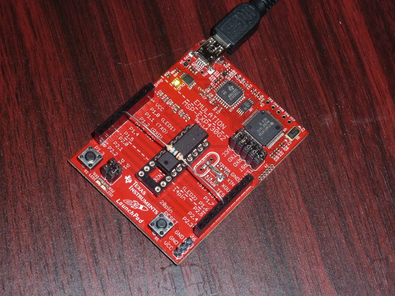
This page is a companion page for my MSP430 Launchpad page.
After learning how to do capacitive touch sensing with an MSP430 over at lcd_i2c.html#_capacitive_touch, I started thinking about something fun I might do with the technique. I thought it might be fun to make a paddle keyer for keying Morse code, so I copied the relevant parts of that page here.
1. Capacitive Touch
Newer MSP430 chips have touch-enabled pins on them. But I discovered while searching for information, that any MSP430 can be programmed to do capacitive touch. This document was very helpful in working out the technique: MSP430 touch pad experiments.pdf. I also found the discussion of sampling from this page helpful: Sample Rate Jittering.
The idea for measuring a capacitive touch plate is pretty straightforward. You just apply a voltage to it and see how long it takes to charge. Apply ground and see how long it takes to discharge. If the time increases, the capacitance has gone up (and that’s what happens when you touch the plate).
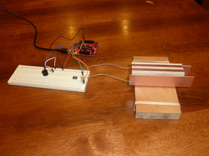
If you wire things correctly, a pair of pins on the MSP430 can monitor a pair of touch plates (which don’t have to be anything special, basically anything metal you can touch). For the examples that follow, I chose pins 1.4 and 1.7 on the MSP430. The configuration is simple. Connect the pins with a large value resistor; typical values I found in reading were 5M ohms and 5.1M ohms. Then connect a lead from pin 1.4 to one plate, and from pin 1.7 to another plate.
2. A Completely Minimal Paddle
You can make a completely minimal touch paddle with only a single 5M ohm resistor and no plates at all. Bend the leads out, and connect pin 1.4 to pin 1.7, with the resistor straddling the MSP430. I took a picture of mine. I used a 10M ohm resistor here, since that is what I had on hand, but I would guess that value is a bit higher that optimal. It worked, but it seemed just a bit slow to recognize touches when I played with it.
This program implements the touch detection. It simply lights one LED if you press the "dot" lead (traditionally, the left paddle). And it lights the other when you press the "dash" lead. I could perhaps modify it later to use a transistor, or maybe an optical isolator, to actually drive the keyer in my transmitter. And of course, I could connect it to real paddles.
#include <msp430g2211.h>

#define RED BIT0
#define GRN BIT6

#define DOT BIT4
#define DASH BIT7

volatile unsigned int timer_count;

/* This triggers when a pad has been charged or discharged.  When it returns,
 * timer_count will hold the elapsed count of charging or discharging time for
 * the key.  Setup for triggering this interrupt happens in
 * measure_key_capacitance(). */
void Port_1 (void) __attribute__((interrupt(PORT1_VECTOR)));
void Port_1 (void) {
    P1IFG = 0;
    timer_count = TAR - timer_count;
    __bic_SR_register_on_exit( LPM0_bits );
}

/* Returns a value the reflects the capacitance of one of two key pads
 * connected by a large value resistor.  Assumes key to be BIT4 or BIT7. */
unsigned int measure_key_capacitance( unsigned int key ) {
    static unsigned int sum;

    P1OUT &= ~(BIT4 + BIT7);    // Start with both keys low.

    /* charge key */
    P1OUT |= key;
    asm( "nop \n\t" "nop \n\t" "nop \n\t" );

    /* Set up interrupt to trigger on key. */
    P1IES |= key;       // Trigger on voltage drop.
    P1IE |= key;        // Interrupt on.
    P1DIR &= ~key;      // Float key and let voltage drop.

    timer_count = TAR;  // Get timer (to compare with in interrupt).
    __bis_SR_register( LPM0_bits + GIE );       // Sleep.

    P1IE &= ~key;       // Disable interrupts on key.
    P1OUT &= ~key;      // Discharge key by setting
    P1DIR |= key;       // active low.

    sum = timer_count;  // Save the count that was recorded in interrupt.

    /* Charge the complement line. */
    P1OUT |= (BIT4 + BIT7)^key;
    asm( "nop \n\t" "nop \n\t" "nop \n\t" );

    /* Set up interrupt to trigger on key. */
    P1IES &= ~key;      // Trigger on voltage rise.
    P1IE |= key;        // Interrupt on.
    P1DIR &= ~key;      // Float key and let voltage rise.

    timer_count = TAR;  // Get timer (to compare with in interrupt).
    __bis_SR_register( LPM0_bits + GIE );

    P1IE &= ~key;       // Disable interrupts on key.
    P1OUT &= ~(BIT4 + BIT7);    // Set both keys to
    P1DIR |=  (BIT4 + BIT7);    // active low.

    return sum + timer_count;   // Return the sum of both counts.
}

/* Computes a trimmed mean of 18 capacitance values, trimming the largest and
 * smallest samples. */
unsigned int sample_key( unsigned char key ) {
    int i, j, small, large, cap;
    long int total;

    total = 0;

    /* Measure once to initialize max and min values. */
    small = large = measure_key_capacitance( key );

    /* Seventeen more samples happen here. Each time we decide whether the new
     * sample is kept or if it replaces one of the extremes. */
    for( i = 1; i < 18; i++ ) {
        cap = measure_key_capacitance( key );
        if( cap < small ) {
            total += small;
            small = cap;
        } else if( cap > large ) {
            total += large;
            large = cap;
        } else {
            total += cap;
        }

        // Add some jitter here, for more effective sampling.
        for( j=0; j < (cap&0x0F); j++ ) asm( "nop \n\t" );
    }

    /* We average 16 values (not including the two extremes) */
    return total >> 4;
}

void WDT(void) __attribute__((interrupt(WDT_VECTOR)));
void WDT(void) {
    /* Wake up the main program. */
    __bic_SR_register_on_exit( LPM0_bits );
}

int main(void) {
    int i, j;
    int flag1=0, flag2=0;
    int baseline1=0, baseline2=0, samp1, samp2;

    /* Stop the watchdog timer so it doesn't reset our chip. */
    WDTCTL = WDTPW + WDTHOLD;

    /* Set clock speed at 1Mhz. */
    BCSCTL1 = CALBC1_1MHZ;
    DCOCTL = CALDCO_1MHZ;

    /* Both LEDs are output lines */
    P1DIR |= RED + GRN;

    /* Setup for capacitive touch.  Timer A is in count up mode, driven by the
     * submain clock (1 Mhz) with a clock divider of 2^2=4. The pins for our
     * touch pads are set as output pins. */
    TACTL = MC_2 + TASSEL_2 + ID_2;     // count up mode, SMCLK, /4
    P1DIR |= DASH + DOT;

    /* Get maximum baseline values for each key.  In the main loop, more than
     * 125% of the baseline value will indicate a touch event. */
    P1OUT |= RED + GRN;         // Visually signal the calibration cycle.
    for( i = 0; i < 32; i++ ) {
        samp1 = sample_key(DASH);
        if( samp1 > baseline1 ) baseline1 = samp1;

        samp2 = sample_key(DOT);
        if( samp2 > baseline2 ) baseline2 = samp2;
    }
    P1OUT &= ~(RED + GRN);      // Lights off, calibration done.

    while( 1 ) {
        WDTCTL = WDTPW + WDTHOLD;       // hold watchdog clock

        samp1 = sample_key(DASH);
        samp2 = sample_key(DOT);

        /* One paddle lights the green light. */
        if( 4*samp1 > 5*baseline1 ) {
            P1OUT |= GRN;
        } else {
            P1OUT &= ~GRN;
        }

        /* The other paddle lights the red. */
        if( 4*samp2 > 5*baseline2 ) {
            P1OUT |= RED;
        } else {
            P1OUT &= ~RED;
        }

        /* Set watchdog timer interval to wake us up in 0.5 ms. */
        WDTCTL = WDT_MDLY_0_5;
        IE1 |= WDTIE;
        /* Go to sleep to save power until awoken by timer. */
        __bis_SR_register(LPM0_bits);
    }
}
The key to the program is the measure_key_capacitance() function. It actually takes two measures of the capacitance of the key; and you get to specify the key, either BIT4 or BIT7. First it charges the key, then measures the time for it to discharge through the 5M ohm resistor (by recording the value of a timer and setting an interrupt to trigger on Port 1 when the voltage has fallen). Then it takes a second reading by discharging the pin, and then charging the plate from the other pin through the same resister (again measuring the time with the Port 1 interrupt handler). The sum of the charge and discharge times becomes our measure of capacitance.
The capacitance values can fluctuate quite a bit, and I read about a couple of different compensating techniques. Effectively, everyone recommends some kind of low pass filter (i.e. code that will minimize the effects of high-frequency oscillations). I tried many different things, but I eventually settled on a trimmed mean. It’s very easy to understand, and it gave me consistent performance.
The sample_key() function simply measures the capacitance of the same key 18 times in succession. It throws out the lowest and highest values and averages the other 16. One other line worth noting in that function is the inner loop of nop instructions. The idea of that is to randomize slightly when the samples are drawn, following ideas of: Sample Rate Jittering.
One other thing that I’ve done here is find the largest of a series of samples for the initial baselines, rather than just taking a single average. That seems to reduce the number of instances where the paddles are just too sensitive (and react to anything coming even near them).
3. An Iambic Keyer
First, it should be said that I’ve never actually used an electronic keyer, except the one I made for this project. I’m still a pretty new ham. So I don’t know if my keyer behaves in ways that experienced hams would appreciate.
There are a few things that I can note readily. The top speed of this keyer is probably fairly limited. I might be able to do better by raising the clock speed to 16mhz, but I haven’t tried that. Speed is probably more fundamentally limited by the time it takes to measure a capacitance.
Another thing to note, is that this keyer does not have a "dot buffer." That is to say, if it is playing a dash and you hit a dot (quickly) in the middle, it will not be remembered. Of course, if you keep the dot keyed, it will be picked up when the dash is finished. I toyed with adding a dot buffer, but it isn’t really compatible with my idea for this program.
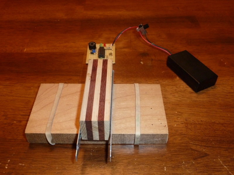
For this program, I wanted something I could practice on. That is, I wanted to be able to key the paddles, and hear the appropriate result. And I wanted to do it with a minimum of parts (two paddles, one resistor, one salvaged electromagnetic transducer, and one Launchpad).
Doing anything while sound is playing creates easily discernible distortion in the tone. For a "real" keyer, where you aren’t trying to play your own sound, but rather where you key an actual radio it could probably be done fine. It would also be not too hard to hook two launchpads together, and let one do the keying and the other create sound (or use a 555 timer, or whatever).
I’ve coded it for the transducer to be hooked between pin P1.1 and ground. I used the red LED to give a visual indicator of inter-letter space, and the green LED to give a visual indicator of word space (so if you see the green light appear between letters instead of words, you are keying too slowly).
The configuration for the touch paddles is:
-
A 5M ohm resistor between pin 1.4 and pin 1.7.
-
Pin 1.4 is connected to the paddle that creates dots (usually the left).
-
Pin 1.7 is connected to the paddle that creates dashes (usually the right).
I connected a transducer that I salvaged from a broken cordless phone (a SoniCrest HC12G pulled from a Uniden phone) between pin 1.1 and ground (with a resistor to keep the volume down so my wife doesn’t go nuts). Jameco part #138722 looks like a good match, though I haven’t tried it.
A little hot glue, and a couple of scrap wood block put together a fairly clean keyer. I found that a couple of rubber bands around the ends of the base made for really good "non-slip feet." Enjoy a picture:
#include <msp430g2211.h>

#define AUDIO BIT1
#define RED BIT0
#define GRN BIT6

#define DOT BIT4
#define DASH BIT7

unsigned int wpm = 8;
unsigned int dotCount = 0, guardSpace = 0;

volatile unsigned int timer_count;

volatile int counter = 0;
volatile unsigned int countAdjust=0;
volatile int toneOn = 0;

volatile int dotKey = 0, dashKey = 0;

/* Key capacitance baseline values. */
unsigned int base_dash, base_dot;

/* State of the keyer.
 * idle: no keys pressed recently
 * dot: sent a dot
 * dash: sent a dash
 */
enum STATES { idle, dot, dash } state = idle;

/* This triggers when a pad has been charged or discharged.  When it returns,
 * timer_count will hold the elapsed count of charging or discharging time for
 * the key.  Setup for triggering this interrupt happens in
 * measure_key_capacitance(). */
void Port_1 (void) __attribute__((interrupt(PORT1_VECTOR)));
void Port_1 (void) {
    P1IFG = 0;
    timer_count = TAR - timer_count;
    __bic_SR_register_on_exit( LPM0_bits );
}

/* Returns a value the reflects the capacitance of one of two key pads
 * connected by a large value resistor.  Assumes key to be BIT7 or BIT4. */
unsigned int measure_key_capacitance( unsigned int key ) {
    static unsigned int sum;

    P1OUT &= ~(BIT7 + BIT4);    // Start with both keys low.

    /* charge key */
    P1OUT |= key;
    asm( "nop \n\t" "nop \n\t" "nop \n\t" );

    /* Set up interrupt to trigger on key. */
    P1IES |= key;       // Trigger on voltage drop.
    P1IE |= key;        // Interrupt on.
    P1DIR &= ~key;      // Float key and let voltage drop.

    timer_count = TAR;  // Get timer (to compare with in interrupt).
    __bis_SR_register( LPM0_bits + GIE );       // Sleep.

    P1IE &= ~key;       // Disable interrupts on key.
    P1OUT &= ~key;      // Discharge key by setting
    P1DIR |= key;       // active low.

    sum = timer_count;  // Save the count that was recorded in interrupt.

    /* Charge the complement line. */
    P1OUT |= (BIT7 + BIT4)^key;
    asm( "nop \n\t" "nop \n\t" "nop \n\t" );

    /* Set up interrupt to trigger on key. */
    P1IES &= ~key;      // Trigger on voltage rise.
    P1IE |= key;        // Interrupt on.
    P1DIR &= ~key;      // Float key and let voltage rise.

    timer_count = TAR;  // Get timer (to compare with in interrupt).
    __bis_SR_register( LPM0_bits + GIE );

    P1IE &= ~key;       // Disable interrupts on key.
    P1OUT &= ~(BIT7 + BIT4);    // Set both keys to
    P1DIR |=  (BIT7 + BIT4);    // active low.

    return sum + timer_count;   // Return the sum of both counts.
}

/* Computes a trimmed mean of 18 capacitance values, trimming the largest and
 * smallest samples. */
unsigned int sample_key( unsigned char key ) {
    long int total;
    int i, j, small, large, cap;

    total = 0;

    /* Measure once to initialize max and min values. */
    small = large = measure_key_capacitance( key );

    /* Seventeen more samples happen here. Each time we decide whether the new
     * sample is kept or if it replaces one of the extremes. */
    for( i = 1; i < 18; i++ ) {
        cap = measure_key_capacitance( key );
        if( cap < small ) {
            total += small;
            small = cap;
        } else if( cap > large ) {
            total += large;
            large = cap;
        } else {
            total += cap;
        }

        // Add some jitter here, for more effective sampling.
        for( j=0; j < (cap&0x0F); j++ ) asm( "nop \n\t" );
    }

    /* We average 16 values (not including the two extremes) */
    return total >> 4;
}

/* Returns 1 if the key is touched (sufficiently past the baseline
 * value) and 0 otherwise.  Sampling can take a fair bit of time, so
 * we adjust the counter for timerA. */
int key_touched( unsigned char key, unsigned int baseline ) {
    unsigned int timeElapsed=0;
    int touch;

    /* Time elapsed is computed to adjust the delay time. */
    timeElapsed = TAR;

    touch = ( 4*sample_key(key) > 5*baseline );

    /* Adjust the delay to account for key sampling time. */
    countAdjust += TAR - timeElapsed;

    return touch;
}

/* This interrupt counts the durations for playing dots and dashes,
 * as well as the durations for dot-spaces and dash-spaces. */
void TimerA0(void) __attribute__((interrupt(TIMERA0_VECTOR)));
void TimerA0(void) {
    CCR0 += 80;

    if( countAdjust >= 80 ) {
        counter -= countAdjust/80;
        countAdjust = countAdjust%80;
    }

    if( counter-- > 0 ) {
        if( toneOn ) {
            P1OUT ^= AUDIO;
        }
    } else {
        /* Wake up main program when count is finished. */
        __bic_SR_register_on_exit(LPM0_bits);
    }
}

void WDT(void) __attribute__((interrupt(WDT_VECTOR)));
void WDT(void) {
    /* wake up the main program. */
    __bic_SR_register_on_exit(LPM3_bits);
}


void do_space_with_polling( int guard, int minwait, int maxwait ) {
    /* Waits the specified amount of time with polling at 4 points, at
     * the beginning, at the end of the guard time, at the end of the minwait
     * and at the end of the maxwait.  Guard space keeps us from accidentally
     * adding another symbol, but a dash is fine after a dot, and a dot is fine
     * after a dash. Assumes guard <= minwait <= maxwait.*/

    if( guard > 0 ) {
        /* Immediately poll for a key, guarding against doubles. */
        if( state != dash ) {
            dashKey = key_touched(DASH, base_dash);
        }

        if( state != dot ) {
            dotKey = key_touched(DOT, base_dot);
        }

        if( dotKey || dashKey ) {
            maxwait = minwait;                  // Return as soon as possible.
        }

        // Sleep past the guard time.
        counter = guard;
        CCR0 = TAR+80;  // 80 * 4us = 320us -- for tone generation (for delay here)
        CCTL0 |= CCIE;
        __bis_SR_register(LPM0_bits + GIE);
        CCTL0 &= ~CCIE;
    }

    if( minwait > guard ) {
        /* Guard time has passed.  Poll for a key. */
        if( !( dotKey || dashKey )) {
            dashKey = key_touched(DASH, base_dash);
            dotKey = key_touched(DOT, base_dot);

            if( (state == dot) && dashKey ) {           // Make sure both keys alternates.
                dotKey = 0;
            }

            if( dotKey || dashKey ) {
                maxwait = minwait;                      // Return as soon as possible.
            }
        }

        // Sleep past the minwait time.
        counter = minwait - guard;
        CCR0 = TAR+80;  // 80 * 4us = 320us -- for tone generation (for delay here)
        CCTL0 |= CCIE;
        __bis_SR_register(LPM0_bits + GIE);
        CCTL0 &= ~CCIE;
    }

    if( maxwait > minwait ) {
        /* Minwait time has passed.  Poll for a key. */
        if( !( dotKey || dashKey )) {
            dashKey = key_touched(DASH, base_dash);
            dotKey = key_touched(DOT, base_dot);

            if( dotKey || dashKey ) {
                return;
            }
        }

        // Sleep to the maxwait time.
        counter = maxwait - minwait;
        CCR0 = TAR+80;  // 80 * 4us = 320us -- for tone generation (for delay here)
        CCTL0 |= CCIE;
        __bis_SR_register(LPM0_bits + GIE);
        CCTL0 &= ~CCIE;
    }

    /* Maxwait time has passed.  Poll for a key. */
    if( !( dotKey || dashKey )) {
        dashKey = key_touched(DASH, base_dash);
        dotKey = key_touched(DOT, base_dot);
    }
}

void play_welcome( char *str ) {
    CCR0 = TAR+80;
    CCTL0 |= CCIE;      // CCR0 interrupt enabled

    while( *str ) {
        toneOn = 1;
        counter = ( *str == '-' ) ? 3*dotCount : dotCount;
        __bis_SR_register(LPM0_bits + GIE);

        P1OUT &= ~AUDIO;

        toneOn = 0;
        counter = dotCount;
        __bis_SR_register(LPM0_bits + GIE);
        str++;
    }

    CCTL0 &= ~CCIE;
}

int main(void) {
    int i, j;
    int flag1=0, flag2=0;
    unsigned int samp1, samp2;

    /* Stop the watchdog timer so it doesn't reset our chip. */
    WDTCTL = WDTPW + WDTHOLD;
    /* Set ACLK to use VLO so we can sleep in LPM3 when idle. */
    BCSCTL3 |= LFXT1S_2;

    /* Set all output pins low. */
    P1OUT = 0x00;
    P1DIR = 0xFF;

    /* Set clock speed at 1Mhz. */
    BCSCTL1 = CALBC1_1MHZ;
    DCOCTL = CALDCO_1MHZ;

    /* Both LEDs are output lines */
    P1DIR |= RED + GRN;
    P1OUT &= ~(RED + GRN);

    /* So is the Audio pin. */
    P1DIR |= AUDIO;
    P1OUT &= ~AUDIO;

    /* One word per minute is 50 dots, which makes each dot 6/5 seconds.  Since
     * there are 1e6/4 clock ticks per second (because of the clock divider),
     * and the counter is moved every 80 ticks, the length of a 1 wpm dot is
     * 1e6/4/80*(6/5) = 3750. */
    dotCount = 3750 / wpm;
    guardSpace = dotCount/2;    // guard space is 1/2 of a dot

    /* Setup for capacitive touch.  Timer A is in count up mode, driven by the
     * submain clock (1 Mhz) with a clock divider of 2^2=4. The pins for our
     * touch pads are set as output pins. Same settings used for tone generation. */
    TACTL = MC_2 + TASSEL_2 + ID_2 + TACLR;     // count up mode, SMCLK, /4

    play_welcome("-.-.");       // "C"

    /* Get maximum baseline values for each key.  In the main loop, more than
     * 125% of the baseline value will indicate a touch event. */
    for( i = 0; i < 32; i++ ) {
        samp1 = sample_key(DASH);
        if( samp1 > base_dash ) base_dash = samp1;

        samp2 = sample_key(DOT);
        if( samp2 > base_dot ) base_dot = samp2;
    }

    play_welcome("--.-");       // "Q"

    while( 1 ) {
        if( !( dotKey || dashKey )) {
            /* One paddle sends dashes. */
            dashKey = key_touched(DASH, base_dash);
            /* The other paddle sends dots. */
            dotKey = key_touched(DOT, base_dot);
        }

        if( dotKey ) {
            state = dot;

            counter = dotCount;
            toneOn = 1;         // Play tone.

            countAdjust = 0;    // no need to adjust during tone
            CCR0 = TAR+80;      // 80 * 4us = 320us -- for tone generation
            CCTL0 |= CCIE;      // CCR0 interrupt enabled
            __bis_SR_register(LPM0_bits + GIE);
            CCTL0 &= ~CCIE;     // CCR0 interrupt disabled
        } else if( dashKey ) {
            state = dash;

            counter = 3*dotCount;
            toneOn = 1;         // Play tone.

            countAdjust = 0;    // no need to adjust during tone
            CCR0 = TAR+80;  // 80 * 4us = 320us -- for tone generation
            CCTL0 |= CCIE;      // CCR0 interrupt enabled
            __bis_SR_register(LPM0_bits + GIE);
            CCTL0 &= ~CCIE;     // CCR0 interrupt disabled
        } else {
            /* Set watchdog timer interval to wake us up in 43.7 ms
             * (normally it would be 16 ms, but the VLO is slower). */
            WDTCTL = WDT_ADLY_16;
            IE1 |= WDTIE;
            /* Go to sleep to save power until awoken by timer. */
            __bis_SR_register(LPM3_bits + GIE);
            /* Hold the watchdog clock. */
            WDTCTL = WDTPW + WDTHOLD;
            continue;
        }

        dotKey = dashKey = 0;

        /* Need at least a dot-space now, maybe more. */
        toneOn = 0;
        P1OUT &= ~AUDIO;

        /* 0. Keys within this first space will add symbols to the current letter.
         * We'll guard for dots after a dot, and dashes after a dash.  We'll accept
         * (sloppy) keys up to half a dot late. */
        do_space_with_polling( guardSpace, dotCount, dotCount+dotCount/2 );

        /* If a key was pressed, go back to the top to process it. */
        if( dotKey || dashKey ) continue;

        state = idle;

        P1OUT |= RED;   // visually indicate dash space between letters

        /* 1.5 Now we finish the dash space, and start a new letter.  No guard time.
         * We'll accept (keys) up to half a dot late, for starting the next letter. */
        do_space_with_polling( 0, dotCount+dotCount/2, 2*dotCount );

        P1OUT &= ~RED;  // end of dash space

        /* If a key was pressed, go back to the top to process it. */
        if( dotKey || dashKey ) continue;

        /* 3.5 Another three and a half dots finishes the word space.  Start with
         * two and a half dots without polling. */

        P1OUT |= GRN;   // visually indicate word space

        counter = 2*dotCount+ dotCount/2;
        CCR0 = TAR+80;  // 80 * 4us = 320us -- for tone generation (for delay here)
        CCTL0 |= CCIE;      // CCR0 interrupt enabled
        __bis_SR_register(LPM0_bits + GIE);
        CCTL0 &= ~CCIE;     // CCR0 interrupt disabled

        P1OUT &= ~GRN;  // visually indicate ready again

        /* 7. A final dot space finishes the word-space. */
        do_space_with_polling( 0, dotCount, dotCount );

        /* Idle.  Loop back to the top. */
    }
}
I poll at select times, measured from the ending time of the previous dot or dash: after 0 dots of space, 0.5 dots, 1 dot, 1.5 dots, 3 dots, 3.5 dots, 6 dots, and 7 dots. It might make the keyer more responsive to poll more often, but I found it tricky to get that just right.
You should see a red light between letters, and a red-green transition between words. If you see the green between letters, or a red between symbols in the same letter, you are keying too slowly. If you fail to see a red between letters, or a green between words, you are keying too quickly.
(If you don’t have a speaker/transducer to connect to pin 1.1, change AUDIO to BIT0 or BIT6 and it will light one of the LEDs instead.)
4. A Standalone Keyer
It took me some missteps, but I really wanted to make my keyer free-standing, without the need for the Launchpad card. The page Design notes: Power was really helpful. They aren’t kidding about the capacitors, by the way. Without the proper filtering capacitors, my program would refuse to run, hang randomly, etc. A bunch of caps are definitely going into my next component order.
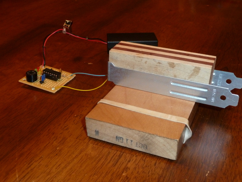
I took a bit of time to rebuild this as a stand-alone circuit, and I added 3 LEDs to my circuit board. One is tied to the audio pin, and glows as code is generated. The other two show the inter-letter and inter-word spaces. On my board, I chose green for the code light, amber for inter-letter space, and red for inter-word space.
The jumper in the picture is for turning off the speaker, so it doesn’t drive my wife nuts. I can still test without sound by watching the LEDs. For paddles, I eventually settled on PCI expansion bay covers salvaged from a broken PC. They worked fine, although it was a bit hard to get solder to stick to them.
To summarize:
-
P1.0 is connected to amber LED (for showing inter-letter space) and 100 ohm current limiting resistor.
-
P1.1 is connected to green LED and 100 ohm current limiting resistor, as well as to the transducer. (The transducer is connected through a jumper so it can be turned off.)
-
P1.6 is connected to red LED (for showing inter-word space) and 100 ohm current limiting resistor.
-
P1.7 is connected to DASH paddle.
-
P1.4 is connected to DOT paddle.
(I used the same 100 ohm resistor for all 3 LEDs putting it between the cathode and ground, and tying all the cathodes together.)
Other connections that were needed:
-
Vcc is connected to the positive terminal of a two AA battery pack.
-
GND is connected to the negative terminal of a two AA pack.
-
Vcc and GND are connected to each other by 0.1uF capacitor.
-
RST is connected to Vcc through a 47K resistor.
-
RST is connected to GND through a 0.001uF capacitor.
When idle, the circuit measures a current draw of 50 uA which means it should run for over a year on a pair of AA batteries, even if on all the time. You’d probably want to turn it off and on to recalibrate, at least when there are significant temperature or humidity changes. When being keyed, it probably draws closer to 15-20mA for lighting the LEDs and playing the buzzer.
5. Commercial circuit board
I decided that I wanted to do up a circuit board for keyer project. It seems that part of the advantage of using a microcontroller is that you can customize your programs to suit different needs. For example, perhaps you only need a really nice touch interface, but your intent is to interface to a ham radio that already has a keyer. In that case you can trim all of the unnecessary program parts and focus on making clean and responsive touch paddle code. Perhaps you want to go even simpler and use it as a straight key.
I tried to plan my board so that it could be used in many different ways. It came back from the fab and it looks pretty nice. So far, I’ve written a couple of different simplified programs to run on it.
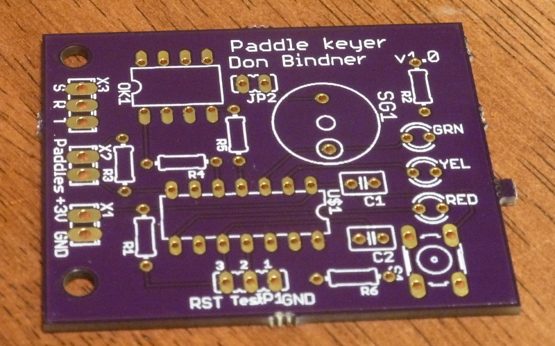
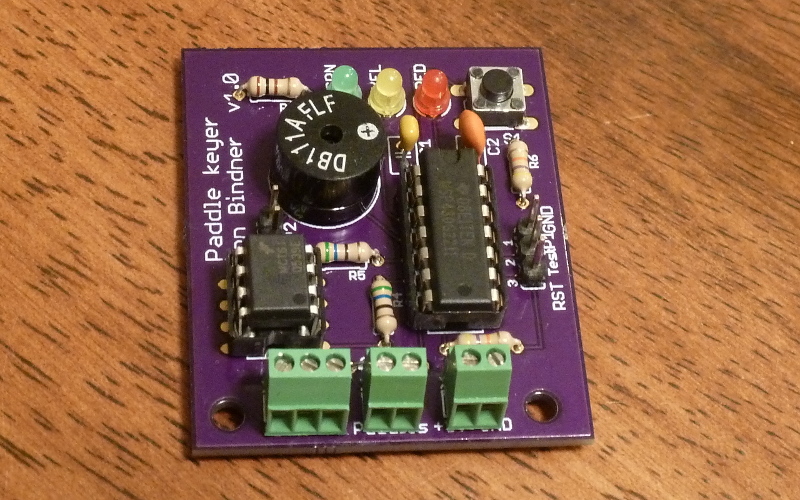
Here’s the board fully populated with components.
I did the board design using CadSoft Eagle. A schematic and board file are here: keyer.sch keyer.brd.
This is the component list:
-
U$1 is a MS430g2211 microcontroller (but the MSP430g2231 or other similar chips should also work).
-
C1 is a 0.1uF capacitor
-
C2 is a 0.001uF (1 nanofarad) capacitor
-
R1 and R6 are 49k ohm resistors
-
R2 is a 100 ohm resistor
-
R3 is a 5M ohm resistor
-
R4 and R5 are 56 ohm resistors
-
RED, YEL, GRN are 3mm LEDs
-
OK1 is an MCT61 optoisolator
-
SG1 is a magnetic transducer (sourced from Jameco)
-
Terminal blocks are TE Connectivity 282834-2 and 282834-3.
Jumper JP2 lets you connect or disconnect the speaker/transducer. Jumper JP1 allows you to program the MSP430 "in place" without having to always remove the chip to a Launchpad card. Simply provide power, then jumper these three lines to a Launchpad for programming.
6. A simple straight key
Probably the conceptually simplest way to run morse code is via a "straight key." In the context of our paddle circuit touching a paddle (either one) will close the key. That’s what the next program achieves, with little fuss. It assumes that any side tone will be generated by your radio, and you only wish the microcontroller to handle the opening and closing of the key.
Many of the components of the board are optional if you want to create a minimal straight key. These are the components you need:
-
U$1: MS430g2211 microcontroller (but the MSP430g2231 or other similar chips should also work).
-
C1: 0.1uF capacitor
-
C2: 0.001uF (1 nanofarad) capacitor
-
R1: 49k ohm resistor
-
R3: 5M ohm resistor
-
R4, R5: 56 ohm resistors
-
OK1: MCT61 optoisolator
-
X1, X2, X3: 282834-2 and 282834-3 (or just solder connections straight to the pads).
You’ll need a way to get the signal into you radio. My Yaesu radio uses a mini stereo connector, so I connected the S, R, and T lines of X3 to the sleeve, ring, and tip of a stereo connector. Then I used a stereo patch cable to connect my radio. Technically, for a straight key, you may not need to connect the ring part of the connection.
You may optionally want to include the yellow and red LEDs and the 100 ohm resistor R3, but the program works fine without them. Here’s the code.
#include <msp430g2211.h>

#define YEL BIT0
#define RED BIT6

#define DOT BIT4
#define DASH BIT5

#define TIP BIT2
#define RING BIT3

volatile unsigned int timer_count;

/* Key capacitance baseline values. */
unsigned int base_dash, base_dot;

/* This triggers when a pad has been charged or discharged.  When it returns,
 * timer_count will hold the elapsed count of charging or discharging time for
 * the key.  Setup for triggering this interrupt happens in
 * measure_key_capacitance(). */
void Port_1 (void) __attribute__((interrupt(PORT1_VECTOR)));
void Port_1 (void) {
    P1IFG = 0;
    timer_count = TAR - timer_count;
    __bic_SR_register_on_exit( LPM0_bits );
}

/* Returns a value the reflects the capacitance of one of two key pads
 * connected by a large value resistor.  Assumes key to be DOT or DASH. */
unsigned int measure_key_capacitance( unsigned int key ) {
    static unsigned int sum;

    P1OUT &= ~(DOT + DASH);    // Start with both keys low.

    /* charge key */
    P1OUT |= key;
    asm( "nop \n\t" "nop \n\t" "nop \n\t" );

    /* Set up interrupt to trigger on key. */
    P1IES |= key;       // Trigger on voltage drop.
    P1IE |= key;        // Interrupt on.
    P1DIR &= ~key;      // Float key and let voltage drop.

    timer_count = TAR;  // Get timer (to compare with in interrupt).
    __bis_SR_register( LPM0_bits + GIE );       // Sleep.

    P1IE &= ~key;       // Disable interrupts on key.
    P1OUT &= ~key;      // Discharge key by setting
    P1DIR |= key;       // active low.

    sum = timer_count;  // Save the count that was recorded in interrupt.

    /* Charge the complement line. */
    P1OUT |= (DOT + DASH)^key;
    asm( "nop \n\t" "nop \n\t" "nop \n\t" );

    /* Set up interrupt to trigger on key. */
    P1IES &= ~key;      // Trigger on voltage rise.
    P1IE |= key;        // Interrupt on.
    P1DIR &= ~key;      // Float key and let voltage rise.

    timer_count = TAR;  // Get timer (to compare with in interrupt).
    __bis_SR_register( LPM0_bits + GIE );

    P1IE &= ~key;       // Disable interrupts on key.
    P1OUT &= ~(DOT + DASH);    // Set both keys to
    P1DIR |=  (DOT + DASH);    // active low.

    return sum + timer_count;   // Return the sum of both counts.
}

/* Computes a trimmed mean of 18 capacitance values, trimming the largest and
 * smallest samples. */
unsigned int sample_key( unsigned char key ) {
    long int total;
    int i, j, small, large, cap;

    total = 0;

    /* Measure once to initialize max and min values. */
    small = large = measure_key_capacitance( key );

    /* Seventeen more samples happen here. Each time we decide whether the new
     * sample is kept or if it replaces one of the extremes. */
    for( i = 1; i < 18; i++ ) {
        cap = measure_key_capacitance( key );
        if( cap < small ) {
            total += small;
            small = cap;
        } else if( cap > large ) {
            total += large;
            large = cap;
        } else {
            total += cap;
        }

        // Add some jitter here, for more effective sampling.
        for( j=0; j < (cap&0x0F); j++ ) asm( "nop \n\t" );
    }

    /* We average 16 values (not including the two extremes) */
    return total >> 4;
}

/* Returns 1 if the key is touched (sufficiently past the baseline
 * value) and 0 otherwise. */
inline int key_touched( unsigned char key, unsigned int baseline ) {
    return ( 4*sample_key(key) > 5*baseline );
}

void WDT(void) __attribute__((interrupt(WDT_VECTOR)));
void WDT(void) {
    /* wake up the main program. */
    __bic_SR_register_on_exit(LPM3_bits);
}

int main(void) {
    int i;
    unsigned int samp1, samp2;

    /* Stop the watchdog timer so it doesn't reset our chip. */
    WDTCTL = WDTPW + WDTHOLD;
    /* Set ACLK to use VLO so we can sleep in LPM3 when idle. */
    BCSCTL3 |= LFXT1S_2;

    /* Set all output pins low. */
    P1OUT = 0x00;
    P1DIR = 0xFF;

    /* Set clock speed at 1Mhz. */
    BCSCTL1 = CALBC1_1MHZ;
    DCOCTL = CALDCO_1MHZ;

    /* Both LEDs are output lines */
    P1DIR |= YEL + RED;
    P1OUT &= ~(YEL + RED);

    /* Setup for capacitive touch.  Timer A is in count up mode, driven by the
     * submain clock (1 Mhz) with a clock divider of 2^2=4. The pins for our
     * touch pads are set as output pins. */
    TACTL = MC_2 + TASSEL_2 + ID_2 + TACLR;     // count up mode, SMCLK, /4

    P1OUT |= YEL + RED;
    /* Get maximum baseline values for each key.  In the main loop, more than
     * 125% of the baseline value will indicate a touch event. */
    for( i = 0; i < 32; i++ ) {
        samp1 = sample_key(DASH);
        if( samp1 > base_dash ) base_dash = samp1;

        samp2 = sample_key(DOT);
        if( samp2 > base_dot ) base_dot = samp2;
    }
    P1OUT &= ~(YEL + RED);

    while( 1 ) {
        if( key_touched( DASH, base_dash ) || key_touched( DOT, base_dot )) {
            P1OUT |= TIP+RING + YEL+RED;
        } else {
            P1OUT &= ~(TIP+RING + YEL+RED);
        }

        /* Set watchdog timer interval to wake us up in 5.2 ms
         * (normally it would be 1.9 ms, but the VLO is slower). */
        WDTCTL = WDT_ADLY_1_9;
        IE1 |= WDTIE;
        /* Go to sleep to save power until awoken by timer. */
        __bis_SR_register(LPM3_bits + GIE);
        /* Hold the watchdog clock. */
        WDTCTL = WDTPW + WDTHOLD;
    }
}
The function of this program is not hard to understand. When the capacitive touch code detects that you’ve touched a paddle, it raises the output lines that go to the input side of the optoisolator. That causes the resistance in the output side of the optoisolator to fall, and the ring and tip connections are brought to ground (exactly as if you closed a physical key/switch). That triggers your radio to generate continuous wave (i.e. Morse code) signal. When you quit touching the paddles, the microcontroller drops its output lines and the optoisolator resistance recovers (as if a physical key/switch were opened).
7. Touch paddles
Only slightly more complex than a straight key, two paddles allows you to connect to a radio and separately indicate dots and dashes. This requires essentially the same components as the straight key:
-
U$1: MS430g2211 microcontroller (but the MSP430g2231 or other similar chips should also work).
-
C1: 0.1uF capacitor
-
C2: 0.001uF (1 nanofarad) capacitor
-
R1: 49k ohm resistor
-
R3: 5M ohm resistor
-
R4, R5: 56 ohm resistors
-
OK1: MCT61 optoisolator
-
X1, X2, X3: 282834-2 and 282834-3 (or just solder connections straight to the pads).
You’ll need a way to get the signal into you radio, just as with the straight key version of the program. My Yaesu radio uses a mini stereo connector, so I connected the S, R, and T lines of X3 to the sleeve, ring, and tip of a stereo connector. Then I used a stereo patch cable to connect my radio. For this version of the program you will need to connect the ring part of the connection.
You may optionally want to include the yellow and red LEDs and the 100 ohm resistor R3, but the program works fine without them. Also, if you include the switch, as well as 49k ohm resistor R6, you’ll be able to reverse the function of paddles on the fly (that is, which paddle generates dots and which generates dashes).
Here’s the code.
#include <msp430g2211.h>

#define SWITCH BIT7

#define YEL BIT0
#define RED BIT6

#define DOT BIT4
#define DASH BIT5

#define TIP BIT2
#define RING BIT3

volatile unsigned int timer_count;
volatile unsigned int bounce_count=0;
volatile unsigned int dash=DASH, dot=DOT;

/* Key capacitance baseline values. */
unsigned int base_dash, base_dot;

/* This triggers when a pad has been charged or discharged.  When it returns,
 * timer_count will hold the elapsed count of charging or discharging time for
 * the key.  Setup for triggering this interrupt happens in
 * measure_key_capacitance().   Also triggers if we press the switch, and
 * schedules a check of the switch after a debouncing delay. */
void Port_1 (void) __attribute__((interrupt(PORT1_VECTOR)));
void Port_1 (void) {
    if( P1IFG & SWITCH ) {
        P1IFG &= ~SWITCH;
        bounce_count = 6;
    }

    if( P1IFG & (DOT+DASH)) {
        P1IFG &= ~(DOT+DASH);
        timer_count = TAR - timer_count;
        __bic_SR_register_on_exit( LPM0_bits );
    }
}

/* Returns a value the reflects the capacitance of one of two key pads
 * connected by a large value resistor.  Assumes key to be DOT or DASH. */
unsigned int measure_key_capacitance( unsigned int key ) {
    static unsigned int sum;

    P1IE &= ~SWITCH;           // Disable switch while we measure.

    P1OUT &= ~(DOT + DASH);    // Start with both keys low.

    /* charge key */
    P1OUT |= key;
    asm( "nop \n\t" "nop \n\t" "nop \n\t" );

    /* Set up interrupt to trigger on key. */
    P1IES |= key;       // Trigger on voltage drop.
    P1IE |= key;        // Interrupt on.
    P1DIR &= ~key;      // Float key and let voltage drop.

    timer_count = TAR;  // Get timer (to compare with in interrupt).
    __bis_SR_register( LPM0_bits + GIE );       // Sleep.

    P1IE &= ~key;       // Disable interrupts on key.
    P1OUT &= ~key;      // Discharge key by setting
    P1DIR |= key;       // active low.

    sum = timer_count;  // Save the count that was recorded in interrupt.

    /* Charge the complement line. */
    P1OUT |= (DOT + DASH)^key;
    asm( "nop \n\t" "nop \n\t" "nop \n\t" );

    /* Set up interrupt to trigger on key. */
    P1IES &= ~key;      // Trigger on voltage rise.
    P1IE |= key;        // Interrupt on.
    P1DIR &= ~key;      // Float key and let voltage rise.

    timer_count = TAR;  // Get timer (to compare with in interrupt).
    __bis_SR_register( LPM0_bits + GIE );

    P1IE &= ~key;       // Disable interrupts on key.
    P1OUT &= ~(DOT + DASH);    // Set both keys to
    P1DIR |=  (DOT + DASH);    // active low.

    P1IE |= SWITCH;            // Re-enable switch.

    return sum + timer_count;   // Return the sum of both counts.
}

/* Computes a trimmed mean of 18 capacitance values, trimming the largest and
 * smallest samples. */
unsigned int sample_key( unsigned char key ) {
    long int total;
    int i, j, small, large, cap;

    total = 0;

    /* Measure once to initialize max and min values. */
    small = large = measure_key_capacitance( key );

    /* Seventeen more samples happen here. Each time we decide whether the new
     * sample is kept or if it replaces one of the extremes. */
    for( i = 1; i < 18; i++ ) {
        cap = measure_key_capacitance( key );
        if( cap < small ) {
            total += small;
            small = cap;
        } else if( cap > large ) {
            total += large;
            large = cap;
        } else {
            total += cap;
        }

        // Add some jitter here, for more effective sampling.
        for( j=0; j < (cap&0x0F); j++ ) asm( "nop \n\t" );
    }

    /* We average 16 values (not including the two extremes) */
    return total >> 4;
}

/* Returns 1 if the key is touched (sufficiently past the baseline
 * value) and 0 otherwise. */
inline int key_touched( unsigned char key, unsigned int baseline ) {
    return ( 4*sample_key(key) > 5*baseline );
}

void WDT(void) __attribute__((interrupt(WDT_VECTOR)));
void WDT(void) {
    if( bounce_count ) {
        bounce_count--;

        /* When count hits 0, it's time to check the switch */
        if( !bounce_count ) {
            if( P1IN & BIT7 ) { // key press, swap dash and dot
                dash ^= DASH+DOT;
                dot ^= DASH+DOT;
            }
        }
    } else {
        /* wake up the main program. */
        __bic_SR_register_on_exit(LPM3_bits);
    }
}

int main(void) {
    int i;
    unsigned int samp1, samp2;

    /* Stop the watchdog timer so it doesn't reset our chip. */
    WDTCTL = WDTPW + WDTHOLD;
    /* Set ACLK to use VLO so we can sleep in LPM3 when idle. */
    BCSCTL3 |= LFXT1S_2;

    /* Set all output pins low. */
    P1OUT = 0x00;
    P1DIR = 0xFF;

    /* Set clock speed at 1Mhz. */
    BCSCTL1 = CALBC1_1MHZ;
    DCOCTL = CALDCO_1MHZ;

    /* Both LEDs are output lines */
    P1DIR |= YEL + RED;
    P1OUT &= ~(YEL + RED);

    /* Set switch as input pin triggering on rise. */
    P1IES &= ~SWITCH;   // Trigger on voltage rise.
    P1IE |= SWITCH;     // Interrupt on.
    P1DIR &= ~SWITCH;   // Input pin.

    /* Setup for capacitive touch.  Timer A is in count up mode, driven by the
     * submain clock (1 Mhz) with a clock divider of 2^2=4. The pins for our
     * touch pads are set as output pins. */
    TACTL = MC_2 + TASSEL_2 + ID_2 + TACLR;     // count up mode, SMCLK, /4

    P1OUT |= YEL + RED;
    /* Get maximum baseline values for each key.  In the main loop, more than
     * 125% of the baseline value will indicate a touch event. */
    for( i = 0; i < 32; i++ ) {
        samp1 = sample_key(DASH);
        if( samp1 > base_dash ) base_dash = samp1;

        samp2 = sample_key(DOT);
        if( samp2 > base_dot ) base_dot = samp2;
    }
    P1OUT &= ~(YEL + RED);

    while( 1 ) {
        if( key_touched( dash, base_dash )) {
            P1OUT |= RING + RED;
        } else {
            P1OUT &= ~(RING + RED);
        }

        if( key_touched( dot, base_dot )) {
            P1OUT |= (TIP + YEL);
        } else {
            P1OUT &= ~(TIP + YEL);
        }

        /* Set watchdog timer interval to wake us up in 5.2 ms
         * (normally it would be 1.9 ms, but the VLO is slower). */
        WDTCTL = WDT_ADLY_1_9;
        IE1 |= WDTIE;
        /* Go to sleep to save power until awoken by timer. */
        __bis_SR_register(LPM3_bits + GIE);
        /* Hold the watchdog clock. */
        WDTCTL = WDTPW + WDTHOLD;
    }
}
This program functions nearly identically to the straight key program, except for two differences. The ring and tip connections are driven independently, and the Port 1 interrupt handler has been adapted to detect when the switch is pressed. A small change was also required in the measure_key_capacitance() function to prevent races when the switch is pressed.