This page is a companion page for my MSP430 Launchpad page.
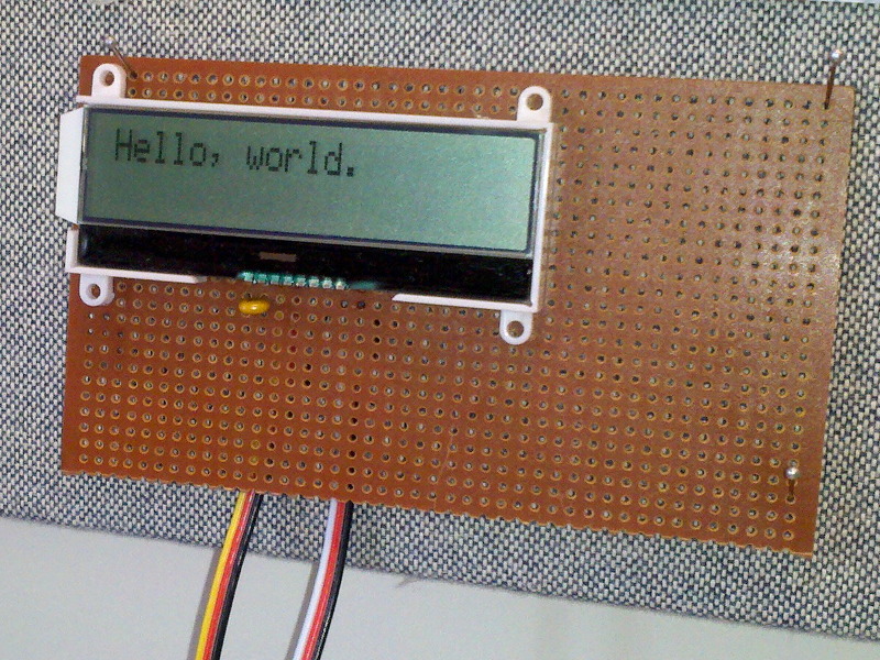
As part of a project with a student, I wanted to get my MSP430 to talk to a relatively inexpensive LCD panel. I chose the Newhaven C0220BIZ-FS(RGB)-FBW-3VM panel, which communicates via an I2C interface. It is a 3.3v part (except the red backlight which wants less), which makes it a natural fit for the MSP430.
We bought our Newhaven displays from Jameco for $11.95 each: Item # 2118539 You may want to pick up at least one 1uF capacitor, and three 10K ohm resistors at the same time (two for the I2C lines, and one for the reset pin).
|
|
The pins of the Newhaven LCD are not set at a standard 0.1" (2.54mm) spacing. I had to gently spread the pins apart to fit the LCD to standard perf board. Basically, I angled a few pins into the perf board at one edge, wiggling slightly to bend the pins as I worked more and more into the holes. You also can’t see the fat pins that run the backlight are hanging off the side of the board, since they don’t fit either. |
1. I2C communications
The I2C communications protocol is a method of doing serial communications that overcomes one of the inherent problems with typical UART serial methods, that of synchronizing the data rate at both ends. (With standard serial communications, you have to be careful to set the same baud rate for the transmitter and receiver, or the communication will fail.)
Only 2 wires are required for I2C communication (plus the power and ground connections), a "data" line and a "clock" line. That is very nice for a microcontroller, like the MSP430, which has a limited number of I/O pins.
The general idea of the communication is easy to understand: a master device puts data on the data line one bit at a time, most significant bit first, and pulses the clock line. Slave devices read the data bits during the pulses. Exact timing is not essential because slaves adapt to whatever speed the master pulses the clock line.
For detailed information about I2C, the Wikipedia page is very good, http://en.wikipedia.org/wiki/I%C2%B2C. The data sheet for the LCD panel also has some relatively simple example code that is a big help. You’ll definitely be wanting to read the data sheet for details on the panel!
2. Wiring up the LCD panel
When looking at the front of the LCD panel, pin 1 is on the right and pin 8 is on the left (page 4 of the data sheet shows the physical diagram). According to the data sheet, you should connect pins 7 and 8 with a 1uF capacitor. You’ll also want to connect pin 6 via a 1uF capacitor to ground (for example, pin 4).
For the code that follows, I made these connections to my MSP430 Launchpad:
-
LCD pin 1 (RST) to MSP430 pin 1.3 (the pin that switch S2 is on).
-
LCD pin 2 (SCL) to MSP430 pin 1.6 (the pin with the green LED).
-
LCD pin 3 (SDA) to MSP430 pin 1.0 (the pin with the red LED).
-
LCD pin 4 (VSS) to MSP430 ground.
-
LCD pin 5 (VDD) to MSP430 Vcc/power.
LCD pins 1, 2, and 3 require pull-up resistors, and two of these are shown on the data sheet. (The reset pin also needs to be pulled up since the data sheet describes it as "active low," and we don’t want the reset button continuously "pushed" because we forgot to wire it up. Nothing will work.)
We can use the internal pull-up resistors in the MSP430, so we won’t need external resistors, but I found physical resistors to be more reliable. On the Launchpad, switch S2 has a pull-up resistor on it already, so that connection is covered. But, I connected 10K ohm resistors between Vcc/power and LCD pins 2 and 3.
Because the clock and data lines are connected to the same pins as the red and green LEDs on the Launchpad, we’ll be able to observe the data communication visually. Later, if we wish, we can remove the jumpers to disconnect the LEDs or switch to different pins on the MSP430.
|
|
If you choose instead to modify the code to use the internal pull-up resistors in the MSP430, then you may not be able to watch the LEDs and have the panel actually work at the same time. I had to remove the jumpers (after verifying that the LEDs light up) to get the communication to work. |
|
|
Since we connected the reset pin of the panel to MSP430 pin 1.3, we can reset the panel as we wish by pressing switch S2. We could also have the microcontroller trigger a reset by outputting a 0 on pin 1.3. |
3. A first I2C program
#include <msp430g2211.h>

#define I2C_SDA BIT0   // Serial Data line
#define I2C_SCL BIT6   // Serial Clock line

/* A crude delay function.  Tune by changing the counter value. */
void delay( unsigned int n ) {
    volatile int i;

    for( ; n; n-- ) {
        for( i = 0; i < 50; i++ );
    }
}

void data_read(void ) {
    P1DIR &= ~I2C_SDA; // float to get ready to read
}

void data_high(void ) {
    P1DIR &= ~I2C_SDA; // float pin to go high
    delay( 5 );
}

void data_low(void ) {
    P1OUT &= ~I2C_SDA; // assert low
    P1DIR |= I2C_SDA;
    delay( 5 );
}

void clk_high(void) {
    P1DIR &= ~I2C_SCL;  // float pin to go high
    delay( 10 );
}

void clk_low(void) {
    P1OUT &= ~I2C_SCL;  // assert low
    P1DIR |= I2C_SCL;
    delay( 5 );
}

/* I2C communication starts when both the data and clock
 * lines go low, in that order. */
void I2C_Start(void) {
    clk_high();
    data_high();
    data_low();
    clk_low();
}

/* I2C communication stops with both the clock and data
 * lines going high, in that order. */
void I2C_Stop(void) {
    data_low();
    clk_low();
    clk_high();
    data_high();
}

/* Outputs 8-bit command or data via I2C lines. */
void I2C_out(unsigned char d) {
    int n;

    for( n = 0; n < 8; n++ ) {
        if( d & 0x80 ) {
            data_high();
        } else {
            data_low();
        }

        clk_high();
        clk_low();

        d <<= 1;        // Shift next bit into position.
    }

    data_read();        // Set data line to receive.
    clk_high();         // Clock goes high to wait for acknowledge.

    // Slave will pull data line low to acknowledge.
    while( P1IN & I2C_SDA ) {
        // Else toggle the clock line and check again
        clk_low();
        clk_high();
    }

    clk_low();
}

/* Initializes the LCD panel. */
void init_LCD(void) {
    I2C_Start();

    I2C_out( 0x78 );    // Slave address of the LCD panel.
    I2C_out( 0x00 );    // Control byte: all following bytes are commands.
    I2C_out( 0x38 );    // 8-bit bus, 2-line display, normal instruction mode.
    delay( 10 );

    I2C_out( 0x39 );    // 8-bit bus, 2-line display, extension instruction mode.
    delay( 10 );

    I2C_out( 0x14 );    // Bias set to 1/5.
    I2C_out( 0x78 );    // Contrast set.
    I2C_out( 0x5E );    // Icon display on, booster on, contrast set.
    I2C_out( 0x6D );    // Follower circuit on, amplifier=1?
    I2C_out( 0x0C );    // Display on, cursor off.
    I2C_out( 0x01 );    // Clear display.
    I2C_out( 0x06 );    // Entry mode set to cursor-moves-right.
    delay( 10 );

    I2C_Stop();
}

/* Sends the "clear display" command to the LCD. */
void clear_display(void) {
    I2C_Start();

    I2C_out( 0x78 ); // Slave address of panel.
    I2C_out( 0x00 ); // Control byte: all following bytes are commands.
    I2C_out( 0x01 ); // Clear display.

    I2C_Stop();
}

/* Writes a 20-char string to the RAM of the LCD. */
void show( unsigned char *text ) {
    int n;

    I2C_Start();

    I2C_out( 0x78 ); // Slave address of panel.
    I2C_out( 0x40 ); // Control byte: data bytes follow, data is RAM data.

    for( n = 0; n < 20; n++ ) {
        I2C_out( *text );
        text++;
    }

    I2C_Stop();
}

int main(void) {
    int i;

    /* Stop the watchdog timer so it doesn't reset our chip */
    WDTCTL = WDTPW + WDTHOLD;

    init_LCD();

    show( "Hello, world.       " );
    clear_display();
    show( "Goodbye, world.     " );

    __bis_SR_register( LPM3_bits );     /* go to sleep */
}
To compile and install:
> msp430-gcc -O2 -mmcu=msp430x2211 -o lcddemo.elf lcddemo.c && mspdebug rf2500 "prog lcddemo.elf"
|
|
If you power cycle the Launchpad (and the LCD, since they’re connected) the program will fail initially to communicate with the panel. That is because the Start condition is set by the MSP430 before the panel is ready to detect it. Simply press switch S1 (the Launchpad reset) to restart the program, and everything will work. |
3.1. I2C discussion
Most of the program should be relatively easy to understand. For this first program, we used a crude delay loop for timing. If you want to slow the timing down, increase the value of the counter in delay(). This will allow you to see, and even count if you wish, the communication bits and the clock pulses on the red and green LEDs of the Launchpad board.
The data_high() and data_low() functions cause a 1 or 0 to be put on the data line. Only the 0, however, is an actively driven value. To put a 1 on the line, we set the pin (which is pin 1.0) to be an input pin, effectively letting it "float." The pull-up resistor then takes care of raising the value to 1.
The clk_high() and clk_low() functions work the same way. We either set pin 1.6 as an output pin and put a 0 on it to drive it low, or we set it as an input pin and let it be pulled high.
|
|
In this application, with a single master and a single slave, there would be no harm to actively setting the clock line to both 1 and 0. In multi-slave and multi-master situations, we would need to be more careful about our manipulation of the clock line (and the data line too). The Wikipedia page on I2C has more details. |
The I2C_Start() function begins each communication. Slaves will know a communication is beginning when the data line transitions from high to low while the clock line is high. (During communication, data line transitions only occur when the clock line is low.) In I2C_Stop() it is the transition of the data line from low to high when the clock line is high that signals the end of the communication.
The I2C_out() function transmits a single 8-bit byte of values on the data line. Then it waits for an acknowledgement from the slave device (the LCD panel). According to the I2C standard, the master should let the data line float and set the clock line high. When the slave is ready to continue, it will acknowledge the byte by pulling the data line low, which will break (or skip) the while loop in our program.
|
|
If your LCD panel is not responding correctly, perhaps because it is miswired or has a different slave address, your program will hang in the while loop. You’ll be able to see this, since the pattern of blinking on the LEDs on the Launchpad will change character (becoming very uniform and continuing forever). |
3.2. LCD panel functions
The init_LCD() code is pulled straight from the Newhaven data sheet, though some comments have been added about what each byte/command does. It needs to be the first thing your program communicates to the LCD.
The clear_display() function gives an example of sending a single command to the LCD.
The show() function copies data sequentially to the RAM of the panel, and assumes it has been called with strings of length 20.
The memory configuration of the LCD panel is worth discussing. This 2-line LCD display has an 80 byte memory (so more memory than can appear on the display). The first 20 bytes of RAM are the characters that show on the first line of the 2-line display. The next 20 bytes of RAM exist off-screen to the right of the first line.
That means that the second line of the display actually fills RAM location 40-59, which is probably not what you would naively expect. Finally, at location 60 there are another 20 characters of off-screen data that exists to the right of the second line.
Here is an example:
    clear_display();
    show( "Hello, world.       " );    // shows on line 1
    show( "12345678901234567890" );    // hidden to the right of line 1
    show( "Goodbye, world.     " );    // shows on line 2
    show( "12345678901234567890" );    // hidden to the right of line 2
    show( "Oh, hello again.    " );    // replaces/shows on line 1
There are commands for scrolling the screen to the left and right to show the "hidden" off-screen text.
3.3. LCD contrast
My LCD panel had the contrast set too high by default, and I could not read my hello world text (it looked instead like two rows of filled black boxes). I found that I could modify the contrast by placing a resistor between Vout (LCD pin 6) and Vdd/Vcc (power). I found 3900 ohms to work well. I have no idea if this is recommended or not, and I plan to experiment with changing the contrast via commands to the panel instead. So, perhaps I can remove this resistor.
4. I2C Multi-master
The I2C protocol allows for multiple masters and multiple slaves to be on the serial bus at once. Each master needs to watch the bus, so it doesn’t initiate communications while another master is already active. We can use interrupts to watch for changes in the data line corresponding to Start and Stop conditions.
Before writing a fully-fledged multi-master capable program, we’ll start first with a short program that detects the start and stop conditions and shows it with LEDs. This program uses pins 1.4 and 1.5 for the data and clock lines to leave free pins 1.0 (red LED) and 1.6 (green LED).
#include <msp430g2211.h>

#define I2C_SDA BIT4   // Data line
#define I2C_SCL BIT5   // Clock line

/* This flag is set if another master is controlling the bus */
int other_master = 0;

/* Catch rising or falling edges of the data line, to check for
 * Start and Stop condition (and sometimes just other traffic). */
void Port_1 (void) __attribute__((interrupt(PORT1_VECTOR)));
void Port_1(void) {
    int status = P1IN;

    /* if clock line is high, then this was Start or Stop */
    if( status & I2C_SCL ) {
        /* if data line fell, then this is a Start */
        if( ( status & I2C_SDA ) == 0) {
            other_master = 1;
            P1OUT |= BIT0;      // red on
        } else { /* this is a Stop */
            other_master = 0;
            P1OUT &= ~BIT0;     // red off
        }
    }

    if( other_master ) {
        P1IES &= ~I2C_SDA;      /* catch next rising edge */
    } else {
        P1IES |= I2C_SDA;       /* catch next falling edge */
    }

    P1IFG &= ~I2C_SDA;  /* clear interrupt flag */
}

int main(void) {
    int i;

    /* Stop the watchdog timer so it doesn't reset our chip */
    WDTCTL = WDTPW + WDTHOLD;

    P1DIR |= BIT0 + BIT6;       // status lights are output pins
    P1OUT &= ~(BIT0 + BIT6);    // start off

    // Enable interrupts on the data line (dropping edge)
    P1IES |= I2C_SDA;   // dropping edge
    P1IFG &= ~I2C_SDA;  // clear the interrupt flag
    P1IE |= I2C_SDA;    // enable interrupt
    __bis_SR_register( GIE );     /* general interrupts enabled */

    while( 1 ) {
        /* While we're waiting for interrupts, we'll blink the
         * green light to show changes in the data line. */
        if( P1IN & I2C_SDA ) {
            P1OUT |= BIT6;      /* green on */
        } else {
            P1OUT &= ~BIT6;     /* green off */
        }
    }
}
Build and install with:
msp430-gcc -O2 -mmcu=msp430x2211 -o i2cmonitor.elf i2cmonitor.c && mspdebug rf2500 "prog i2cmonitor.elf"
5. A multi-master I2C bit-banger
This code implements a multi-master I2C interface via bit-banging. That is, it is an I2C master that watches the serial bus for activity from other masters and waits its turn to communicate. It can also detect when another master starts communicating simultaneously (and drops out to let the other master continue).
#include <msp430g2211.h>

#define I2C_SDA BIT4   // Data line
#define I2C_SCL BIT5   // Clock line

int other_master = 0;
int we_are_master = 0;

/* A crude delay function.  Tune by changing the constant. */
inline void delay( unsigned int n ) {
    volatile unsigned int i = n<<2;
    while( i-- ) ;
}

inline void data_read(void ) {
    P1DIR &= ~I2C_SDA; // float to get ready to read
}

inline void data_high(void ) {
    P1DIR &= ~I2C_SDA; // float pin to go high
    delay( 5 );
}

inline void data_low(void ) {
    P1DIR |= I2C_SDA;
    delay( 5 );
}

void clk_high(void) {
    P1DIR &= ~I2C_SCL;  // float pin to go high

    int i = 100;
    while( !(P1IN & I2C_SCL) && i-- ) ; // clock stretching

    delay( 10 );
}

inline void clk_low(void) {
    P1DIR |= I2C_SCL;
    delay( 5 );
}

inline int data_pulled_down(void) {
    return ! (P1IN & I2C_SDA );
}

/* Catch rising or falling edges of the data line, to check for
 * Start and Stop condition (and sometimes just other traffic). */
void Port_1 (void) __attribute__((interrupt(PORT1_VECTOR)));
void Port_1(void) {
    int status = P1IN;

    /* If both lines are high, we just saw a Stop condition.
     * Otherwise, another master has the bus. */
    if(( status & I2C_SCL ) && (status & I2C_SDA )) {
        other_master = 0;
        P1OUT |= BIT6;          // green light on
        P1OUT &= ~BIT0;         // red light off
        P1IES |= I2C_SDA;       // catch next fall
    } else {
        other_master = 1;
        P1OUT &= ~BIT6;         // green light off
        P1IES &= ~I2C_SDA;      // catch next rise
    }

    P1IFG &= ~I2C_SDA;  /* clear interrupt flag */
}

/* If we discover another master on the bus while we are communicating,
 * we need to abort our communication and watch for Stop condition
 * before continuing. */
inline void lost_arbitration() {
    other_master = 1;

    P1IES &= ~I2C_SDA;  // catch next rising edge
    P1IE |= I2C_SDA;    // enable interrupt
    P1IFG &= ~I2C_SDA;  // clear interrupt flag

    we_are_master = 0;

    P1OUT ^= BIT0+BIT6; // toggle red on and green off
}

/* I2C communication starts when both the data and clock
 * lines go low, in that order. */
void I2C_Start(void) {
    if( other_master ) return;

    clk_high();
    data_high();

    if( data_pulled_down()) {   // someone else has the bus
        lost_arbitration();
        return;
    }

    /* stop processing data line interrupts */
    P1IE &= ~I2C_SDA;

    data_low();
    clk_low();

    we_are_master = 1;
}

/* I2C communication stops with both the clock and data
 * lines going high, in that order. */
void I2C_Stop(void) {
    if( ! we_are_master ) return;

    data_low();
    clk_low();

    /* Resume watching for Start condition (falling data edge). */
    P1IES |= I2C_SDA;
    P1IE |= I2C_SDA;
    P1IFG &= ~I2C_SDA;

    clk_high();
    data_high();

    we_are_master = 0;
}

/* Outputs 8-bit command or data via I2C lines. */
void I2C_out(unsigned char d) {
    int n;

    if( ! we_are_master ) return;

    for( n = 0; n < 8; n++ ) {
        if( d & 0x80 ) {
            data_high();
            clk_high();

            /* If the line is 0, some other master is
             * controlling the line, and we should drop out. */
            if( data_pulled_down()) {
                lost_arbitration();
                return;
            }
        } else {
            data_low();
            clk_high();
        }

        clk_low();

        d <<= 1;        // Shift next bit into position.
    }

    data_read();        // Set data line to receive.
    clk_high();         // Clock goes high to wait for acknowledge.

    // Slave will pull data line low to acknowledge.
    int i = 20;
    while( P1IN & I2C_SDA ) {
        // Else toggle the clock line and check again
        clk_low();
        clk_high();

        // Timeout eventually, leaving Stop condition.
        if( ! --i ) {
            I2C_Stop();
            return;
        }
    }

    clk_low();
}

/* Initializes the LCD panel. */
void init_LCD(void) {
    I2C_Start();

    I2C_out( 0x78 );    // Slave address of the LCD panel.
    I2C_out( 0x00 );    // Control byte: all following bytes are commands.
    I2C_out( 0x38 );    // 8-bit bus, 2-line display, normal instruction mode.
    delay( 10 );

    I2C_out( 0x39 );    // 8-bit bus, 2-line display, extension instruction mode.
    delay( 10 );

    I2C_out( 0x14 );    // Bias set to 1/5.
    I2C_out( 0x78 );    // Contrast set.
    I2C_out( 0x5E );    // Icon display on, booster on, contrast set.
    I2C_out( 0x6D );    // Follower circuit on, amplifier=1?
    I2C_out( 0x0C );    // Display on, cursor off.
    I2C_out( 0x01 );    // Clear display.
    I2C_out( 0x06 );    // Entry mode set to cursor-moves-right.
    delay( 10 );

    I2C_Stop();
}

/* Sends the "clear display" command to the LCD. */
void clear_display(void) {
    I2C_Start();

    I2C_out( 0x78 ); // Slave address of panel.
    I2C_out( 0x00 ); // Control byte: all following bytes are commands.
    I2C_out( 0x01 ); // Clear display.

    I2C_Stop();
}

/* Writes a 40-char string to the RAM of the LCD. */
void show40( unsigned char *text ) {
    int n;

    I2C_Start();

    I2C_out( 0x78 ); // Slave address of panel.
    I2C_out( 0x40 ); // Control byte: data bytes follow, data is RAM data.

    for( n = 0; n < 40; n++ ) {
        I2C_out( *text++ );
    }

    I2C_Stop();
}

int main(void) {
    int i;

    /* Stop the watchdog timer so it doesn't reset our chip */
    WDTCTL = WDTPW + WDTHOLD;

    /* Only output lines are the lights, which start green on, red off */
    P1DIR |= BIT0 + BIT6;

    /* Data and clock lines are read pins that go low when set for output */
    P1DIR &= ~(I2C_SDA + I2C_SCL);
    P1OUT &= ~( I2C_SDA + I2C_SCL );

    /* We use an interrupt handler to detect start/stop conditions,
     * and some arbitration errors. */
    if( P1IN & I2C_SDA ) {
        P1OUT |= BIT6;          // green on to show bus clear
        P1IES |= I2C_SDA;       // trigger on falling edge
    } else {
        P1OUT &= ~BIT6;         // off to show someone on the bus
        P1IES &= ~I2C_SDA;      // trigger on rising edge
    }
    P1IE |= I2C_SDA;            // enable interrupt
    P1IFG &= ~I2C_SDA;          // clear interrupt flag
    __bis_SR_register( GIE );   // general interrupt enable

    delay(400);

    init_LCD();
    delay(99);

#if 1
    srand(100);
    while( 1 ) {
        show40( "1 1 1 1 1           1-1-1-1-1-----------" );
        delay( rand()%9 );
        show40( "1+1+1+1+1+++++++++++1*1*1*1*1***********" );
        delay( rand()%9 );
        show40( "1/1/1/1/1///////////1=1=1=1=1===========" );
        delay( rand()%9 );
    }
#else
    srand(200);
    while( 1 ) {
        show40( " 2 2 2 2 2          -2-2-2-2-2----------" );
        delay( rand()%9 );
        show40( "+2+2+2+2+2++++++++++*2*2*2*2*2**********" );
        delay( rand()%9 );
        show40( "/2/2/2/2/2//////////=2=2=2=2=2==========" );
        delay( rand()%9 );
    }
#endif
}
There’s a fair bit of new stuff in this program. One small addition right at the beginning is in clk_high(). After the clock line is raised, a loop checks to ensure that another device is not still holding the clock line low, and waits for the other device to let go. This allows slower devices to invoke "clock stretching," effectively slowing down the interface. The loop eventually times out, but the duration can be tuned if necessary by changing the number of iterations of the loop.
The Port1 interrupt handler is used to detect when another master has control of the bus. It is somewhat modified from the monitor program. The main change is a logical reorganization, based on the premise that we can divide events into two types, either the Stop condition has been triggered, or another master has the bus. There is no need to distinguish a Start from any other kind of active use of the bus.
The lost_arbitration() function exists for situations where we thought we were the sole master on the serial bus and then discovered that another master is also using the bus. In every case, this is discovered when the data line has been pulled low while we expected it to be high. This function resets the global flags and interrupts, so we can wait for the bus to become free.
The I2C_Start() and I2C_Stop() functions are only slightly changed. Each makes appropriate changes to the interrupt handling behavior and global variables, reflecting that we are taking control of or releasing the bus. The start function checks for arbitration losses.
Similarly, the I2C_out() function checks after every 1 (high) bit to make sure another master is not pulling the data line low. We relinquish the bus if there is such a conflict. The ACK check is also slightly modified to specifically invoke the Stop condition in the case of a timeout of the loop.
None of the other changes are related to I2C. The show40() routine was modified to write an entire line of the LCD (even the invisible right half of the display). And the main() method was divided into separate ifdef divided sections to make it easier to rebuild the program for two different Launchpads connected together. Buy putting different strings on each chip, we can tell which one is successfully communicating with the LCD. Change the 1 to a 0 to build the alternative program.
Build and install with:
msp430-gcc -O2 -mmcu=msp430x2211 -o lcddemo2.elf lcddemo2.c && mspdebug rf2500 "prog lcddemo2.elf"
Each board will light the green LED when it believes the bus is free to use (or when it is actually acting as the master). When the program detects that another device is on the bus, the green LED goes out.
If a program is communicating with the bus and loses arbitration, then the green light will toggle off and the red light will come on. This will last until a stop condition is detected. At that point, the red light goes off and the green comes back on.
This code is pretty reliable, but I found it was rare yet possible for both programs to relinquish the bus with an arbitration error (presumably the LCD panel did something), and then a dead-lock condition occurs with everyone waiting on everyone else. For most reliable operation, there is probably just enough room on the 2K ROM to add a timeout handler and reset things. If no activity has been detected in several seconds after an error, then it’s probably safe to resume. (We may need to trigger the reset pin of the LCD and send another initialization sequence.)
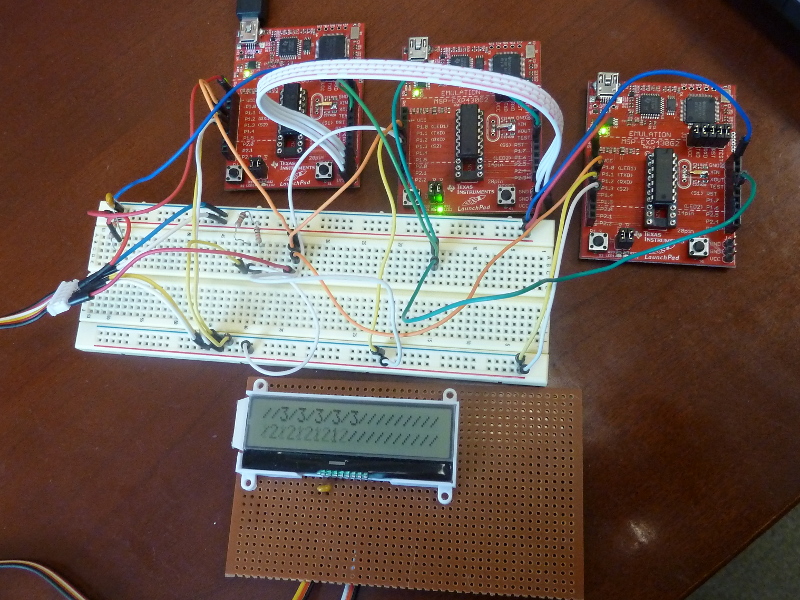
Here’s a picture of 3 Launchpads running this code. There are a few extra wires not strictly required to make it go. For convenience, I connected all of the S1 switches together and all of the S2 switches together (so I could reset the boards simultaneous or reset the LCD by pushing the switches on any board). Notice that the green light is lit on the second board (because it was controlling the bus), and if you look at the LCD, you can see that the second row was caught by the camera just as it was changing to 2s.
6. Messages in memory
I have an idea to make a little sign that scrolls between different messages. So far, my I2C code uses almost all of the 2K Flash memory of my MSP430 chips, which doesn’t leave much room for messages. You can check the size of an MSP430 binary with the msp430-size utility, like this:
c$ msp430-size lcddemo2.elf
   text    data     bss     dec     hex filename
   1964       4       4    1972     7b4 lcddemo2.elf
6.1. Adding a memory chip
To hold my messages, I intend to use a Microchip brand 24LC512-I/P Flash chip. It can hold 512 kilobits of data (or 512÷8=64 kilobytes) in pages of 128 bytes. You read and write data from the chip using the I2C protocol, so I can re-use the I2c code that I already have.
I ordered mine from Newark, part # 62K0581. Sparkfun also has a 256kb version at the time of this writing.
Compared to the LCD panel, I found the memory chip very simple to wire up. There are 8 pins. Pin 4 is Vss and is connected to ground. Diagonally opposite, pin 8 is Vcc and connected to power.
Pins 1, 2, and 3 are used to specify 3 bits of the memory chip’s I2C address (so you can configure up to 8 different memory chips on the same bus). The data sheet simply stated that each should be "tied" to Vcc or Vss to set a single 1 or 0. It did not say whether a resistor was required, but it didn’t seem to hurt. I connected all three pins, together with the write protect pin (pin 7) through a 10K ohm resister to ground.
Finally, pin 5 is SDA, which I connected to the SDA of the microcontroller and the LCD. And pin 6 is SCL, which I connected to the SCL of the microcontroller and the LCD. The master on the I2C bus will be the MSP430, and it will have two slaves.
6.2. LCD changes
I went back to the data sheet to learn how to control the contrast of the LCD panel. It was pretty straightforward to control during the initialization step, and I have now removed the 3900 ohm resistor connecting the LCD Vout and Vdd/Vcc pins.
I’ve also added some helper functions to write messages in specified locations of the LCD RAM. That way I can choose to write a new message on the second line or randomly at any position on screen.
6.3. I2C changes
To make space for new code, I decided that for this program I won’t worry about multi-master scenarios. I removed the interrupt handler and code that watched for other masters on the bus. I did leave the clock stretching code.
One new addition to the I2C code is the function I2C_in() which reads data from a slave. I didn’t need that for the LCD panel, but now that we want to read from a flash chip, that will be important. It take a single argument, a flag whether to acknowledge the byte or not (the convention is to acknowledge every byte except the last one). Perhaps, this should be rewritten to read an array of bytes, but this works for now.
#include <msp430g2211.h>

#define I2C_SDA BIT7   // Data line
#define I2C_SCL BIT6   // Clock line

// Legal contrast values from 0 to 63
#define CONTRAST 30
#define CLOW  (CONTRAST & 0x0F)
#define CHIGH ((CONTRAST>>4) & 0x03)

int error_occurred = 0;
int we_are_master = 0;

/* A crude delay function.  Tune by changing the constant. */
inline void delay( unsigned int n ) {
    volatile unsigned int i = n<<2;
    while( i-- ) ;
}

inline void data_read(void ) {
    P1DIR &= ~I2C_SDA; // float to get ready to read
}

inline void data_high(void ) {
    P1DIR &= ~I2C_SDA; // float pin to go high
    delay( 5 );
}

inline void data_low(void ) {
    P1DIR |= I2C_SDA;
    delay( 5 );
}

void clk_high(void) {
    P1DIR &= ~I2C_SCL;  // float pin to go high

    int i = 100;
    while( !(P1IN & I2C_SCL) && i-- ) ; // clock stretching

    delay( 10 );
}

inline void clk_low(void) {
    P1DIR |= I2C_SCL;
    delay( 5 );
}

inline int data_pulled_down(void) {
    return ! (P1IN & I2C_SDA );
}

inline int data_pulled_up(void) {
    return (P1IN & I2C_SDA );
}

/* As sole master, we should never lose arbitration.
 * This is more of an error check. */
inline void lost_arbitration() {
    we_are_master = 0;
    error_occurred = 1;

    P1OUT ^= BIT0; // toggle red
}

/* I2C communication starts when both the data and clock
 * lines go low, in that order. */
void I2C_Start(void) {
    clk_high();
    data_high();

    if( data_pulled_down()) {   // someone else has the bus
        lost_arbitration();
        return;
    }

    data_low();
    clk_low();

    we_are_master = 1;
}

/* I2C communication stops with both the clock and data
 * lines going high, in that order. */
void I2C_Stop(void) {
    if( ! we_are_master ) return;

    data_low();
    clk_low();

    clk_high();
    data_high();

    we_are_master = 0;
}

/* Outputs 8-bit command or data via I2C lines. */
void I2C_out(unsigned char d) {
    int n;

    if( ! we_are_master ) return;

    for( n = 0; n < 8; n++ ) {
        if( d & 0x80 ) {
            data_high();
            clk_high();

            /* If the line is 0, some other master is
             * controlling the line, and we should drop out. */
            if( data_pulled_down()) {
                lost_arbitration();
                return;
            }
        } else {
            data_low();
            clk_high();
        }

        clk_low();

        d <<= 1;        // Shift next bit into position.
    }

    data_read();        // Set data line to receive.
    clk_high();         // Clock goes high to wait for acknowledge.

    // Slave will pull data line low to acknowledge.
    int i = 20;
    while( P1IN & I2C_SDA ) {
        // Else toggle the clock line and check again
        clk_low();
        clk_high();

        // Timeout eventually, leaving Stop condition.
        if( ! --i ) {
            I2C_Stop();
            return;
        }
    }

    clk_low();
}

/* Inputs 8-bit data from slave, with or without acknowledgement. */
unsigned char I2C_in(int ack) {
    int n;
    unsigned char byte = 0;

    if( ! we_are_master ) return 0;

    data_read();                // Float line to read bits.
    for( n = 0; n < 8; n++ ) {
        byte <<= 1;             // Shift bits over to make room for new bit.

        clk_high();

        if( data_pulled_up()) {
            byte |= 1;          // Slave sent a 1.
        }

        clk_low();
    }

    /* If we need to acknowledge, we'll pull down the data line. */
    if( ack ) {
        data_low();
    }

    clk_high();
    clk_low();

    return byte;
}

/* Initializes the LCD panel. */
void init_LCD(void) {
    I2C_Start();

    I2C_out( 0x78 );    // Slave address of the LCD panel.
    I2C_out( 0x00 );    // Control byte: all following bytes are commands.
    I2C_out( 0x38 );    // 8-bit bus, 2-line display, normal instruction mode.
    delay( 10 );

    I2C_out( 0x39 );    // 8-bit bus, 2-line display, extension instruction mode.
    delay( 10 );

    I2C_out( 0x14 );    // Bias set to 1/5.
    I2C_out( 0x70 | CLOW );    // Contrast set.
    I2C_out( 0x5C | CHIGH);    // Icon display on, booster on, contrast set.
    I2C_out( 0x6D );    // Follower circuit on, amplifier=1?
    I2C_out( 0x0C );    // Display on, cursor off.
    I2C_out( 0x01 );    // Clear display.
    I2C_out( 0x06 );    // Entry mode set to cursor-moves-right.
    delay( 10 );

    I2C_Stop();
}

/* Sends the "clear display" command to the LCD. */
void clear_display(void) {
    I2C_Start();

    I2C_out( 0x78 ); // Slave address of panel.
    I2C_out( 0x00 ); // Control byte: all following bytes are commands.
    I2C_out( 0x01 ); // Clear display.

    I2C_Stop();
}

/* Shows a string of bytes on the LCD at the current position */
void show( unsigned char *bytes, int n ) {
    I2C_Start();

    I2C_out( 0x78 ); // Slave address of panel.
    I2C_out( 0x40 ); // Control byte: data bytes follow, data is RAM data.

    while ( n-- ) {
        I2C_out( *bytes++ );   // Put character.
    }

    I2C_Stop();
}

/* Shows a string of bytes on the LCD beginning from
 * the specified address/position. */
void showAt( int addr, unsigned char *bytes, int n ) {
    I2C_Start();

    I2C_out( 0x78 );            // Slave address of panel.
    I2C_out( 0x80 );            // Next byte is command, followed by control byte.
    I2C_out( 0x80 | addr );     // move to address addr
    I2C_out( 0x40 );            // Control byte: data bytes follow, data is RAM data.

    while ( n-- ) {
        I2C_out( *bytes++ );   // Put character.
    }

    I2C_Stop();
}

/* Reads a sequential string of n bytes from Flash at the
 * current addr.  Assumes n>=1. */
void readNextByteSeq( unsigned char *c, int n ) {
    I2C_Start();
    I2C_out( 0xa1 );            // Slave address for reading

    while( n>1 ) {
        *c++ = I2C_in( 1 );     // Read byte with ACK.
        n--;
    }

    *c = I2C_in( 0 );           // Don't ACK the last byte.

    I2C_Stop();
}

/* Reads the next byte of Flash from the current addr. */
unsigned char readNextByte( void ) {
    unsigned char byte;

    readNextByteSeq( &byte, 1 );        // Read a single byte.

    return byte;
}

/* Read byte from Flash starting at the specified address.  Sends
 * a Start condition, but the (Restart and) Stop is done
 * by the readNextByteSeq() function. */
void readByteSeqAt( unsigned int addr, unsigned char *c, int n ) {
    I2C_Start();
    I2C_out( 0xa0 );            // Slave address for writing/addressing

    I2C_out( addr >> 8 );       // Address high byte
    I2C_out( addr & 0xff );     // Address low byte

    /* Data line is high from last write, so we are ready
     * for another Start sequence. */

    readNextByteSeq( c, n );    // Read a sequence of bytes.
}

/* Read a byte from Flash at the specified address.  Sends
 * a Start condition, but the (Restart and) Stop is done
 * by the readNextByteSeq() function. */
unsigned char readByteAt( unsigned int addr ) {
    unsigned char byte;

    readByteSeqAt( addr, &byte, 1 );    // Read a single byte.

    return byte;
}

/* Write bytes to Flash starting at the specified address. */
void writeByteSeqAt( unsigned int addr, unsigned char *c, int n ) {
    I2C_Start();
    I2C_out( 0xa0 );            // Slave address for writing/addressing

    I2C_out( addr >> 8 );       // Address high byte
    I2C_out( addr & 0xff );     // Address low byte

    while( n>0 ) {
        I2C_out( *c++ );
        n--;
    }

    I2C_Stop();

    /* Wait for write sequence to complete.  Attempt to start a
     * new communication and check for an ACK. */
    do {
        I2C_Start();
        I2C_out( 0xa0 );
    } while( ! we_are_master );

    /* finally got an ACK, so we can continue */
    I2C_Stop();
}

/* Write a single byte at the specified address */
void writeByteAt( unsigned int addr, unsigned char byte ) {
    writeByteSeqAt( addr, &byte, 1 );
}

int main(void) {
    int i;
    unsigned char buffer[10] = "whitestar";
    unsigned char buffer1[10] = "blackstar";

    /* Stop the watchdog timer so it doesn't reset our chip */
    WDTCTL = WDTPW + WDTHOLD;

    /* Only output line is red, which starts off */
    P1DIR |= BIT0;
    P1OUT &= ~BIT0;

    /* Data and clock lines are read pins that go low when set for output */
    P1DIR &= ~(I2C_SDA + I2C_SCL);
    P1OUT &= ~( I2C_SDA + I2C_SCL );

    delay(400);

    init_LCD();
    delay(99);

    // Read starting bytes of memory
    //writeByteSeqAt( 0, buffer, sizeof(buffer));
    //writeByteSeqAt( 0, buffer1, sizeof(buffer1));
    readByteSeqAt( 0, buffer, sizeof(buffer));

    // Show message on second line of the LCD
    showAt( 0x40, buffer, sizeof(buffer));
}
|
|
I found it a little unclear that the second line of the screen starts at memory location 0x40 in the display. Apparently, if you load data sequentially into the display, it loads locations 0-39 (decimal), then skips to 64-103 (decimal). I initially thought the 0x40 in the data sheet was simply a mistake, since it was the 40th character loaded, but apparently not. |
Uncomment the writeByteSeqAt() calls in the main method to record new data into the Flash chip.
7. Capacitive Touch
Newer MSP430 chips have touch-enabled pins on them. But I discovered while searching for information, that any MSP430 can be programmed to do capacitive touch. This document was very helpful in working out the technique: MSP430 touch pad experiments.pdf. I also found the discussion of sampling from this page helpful: Sample Rate Jittering.
The idea for measuring a capacitive touch plate is pretty straightforward. You just apply a voltage to it and see how long it takes to charge. Apply ground and see how long it takes to discharge. If the time increases, the capacitance has gone up (and that’s what happens when you touch the plate).
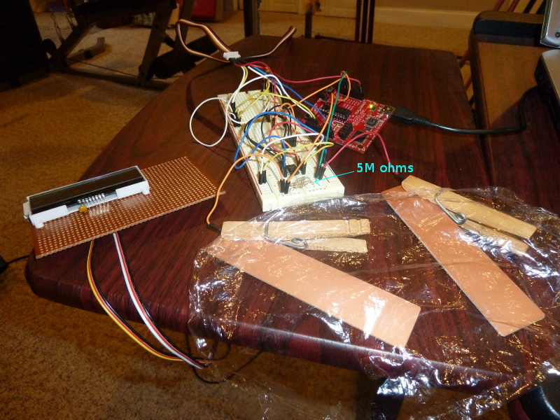
If you wire things correctly, a pair of pins on the MSP430 can monitor a pair of touch plates (which don’t have to be anything special, basically anything metal you can touch). For my experiment, I chose pins 4 and 5. The configuration is simple. Connect the pins with a large value resistor; typical values I found in reading were 5M ohms and 5.1M ohms. Then connect a lead from pin 4 to one plate, and from pin 5 to another plate.
For my plates, I initially just used two jumper wires, and I touched the bare unconnected ends. But I think I may eventually want to use the technique to make a Morse code keyer, and I’ll actually want plates to touch. So I stopped at Radio Shack and bought some 2-sided copper clad (not knowing if it would be better if the back side were grounded). I scored it and snapped off two small strips.
Here’s a picture of my experiment. I labeled the resistor, which is actually five 1M ohm resistors in series, since that’s the largest value I had on hand. The I2C memory chip is still on my breadboard, but that isn’t relevant to this experiment. You can clearly see plastic wrap covering my plates (to verify that you don’t actually have to touch the plate electrically to get it to work).
Most of the code is copied from my previous I2C projects. The most interesting new parts are:
-
A Port 1 interrupt handler
-
The measure_key_capacitance() function, which is the most important new part.
-
The sample_key() function, which helps eliminate the effect of noise.
Check out the code. Then we can discuss.
#include <msp430g2211.h>

#define I2C_SDA BIT7   // Data line
#define I2C_SCL BIT6   // Clock line

// Legal contrast values from 0 to 63
#define CONTRAST 30
#define CLOW  (CONTRAST & 0x0F)
#define CHIGH ((CONTRAST>>4) & 0x03)

/* This has to be volatile, so the compiler knows it may change.
 * Otherwise, optimizations will make you sorry! */
volatile unsigned int timer_count;

int error_occurred = 0;
int we_are_master = 0;

/* A crude delay function.  Tune by changing the constant. */
inline void delay( unsigned int n ) {
    volatile unsigned int i = n<<2;
    while( i-- ) ;
}

inline void data_read(void ) {
    P1DIR &= ~I2C_SDA; // float to get ready to read
}

inline void data_high(void ) {
    P1DIR &= ~I2C_SDA; // float pin to go high
    delay( 5 );
}

inline void data_low(void ) {
    P1DIR |= I2C_SDA;
    delay( 5 );
}

void clk_high(void) {
    P1DIR &= ~I2C_SCL;  // float pin to go high

    int i = 100;
    while( !(P1IN & I2C_SCL) && i-- ) ; // clock stretching

    delay( 10 );
}

inline void clk_low(void) {
    P1DIR |= I2C_SCL;
    delay( 5 );
}

inline int data_pulled_down(void) {
    return ! (P1IN & I2C_SDA );
}

inline int data_pulled_up(void) {
    return (P1IN & I2C_SDA );
}

/* As sole master, we should never lose arbitration.
 * This is more of an error check. */
inline void lost_arbitration() {
    we_are_master = 0;
    error_occurred = 1;

    P1OUT ^= BIT0; // toggle red
}

/* I2C communication starts when both the data and clock
 * lines go low, in that order. */
void I2C_Start(void) {
    clk_high();
    data_high();

    if( data_pulled_down()) {   // someone else has the bus
        lost_arbitration();
        return;
    }

    data_low();
    clk_low();

    we_are_master = 1;
}

/* I2C communication stops with both the clock and data
 * lines going high, in that order. */
void I2C_Stop(void) {
    if( ! we_are_master ) return;

    data_low();
    clk_low();

    clk_high();
    data_high();

    we_are_master = 0;
}

/* Outputs 8-bit command or data via I2C lines. */
void I2C_out(unsigned char d) {
    int n;

    if( ! we_are_master ) return;

    for( n = 0; n < 8; n++ ) {
        if( d & 0x80 ) {
            data_high();
            clk_high();

            /* If the line is 0, some other master is
             * controlling the line, and we should drop out. */
            if( data_pulled_down()) {
                lost_arbitration();
                return;
            }
        } else {
            data_low();
            clk_high();
        }

        clk_low();

        d <<= 1;        // Shift next bit into position.
    }

    data_read();        // Set data line to receive.
    clk_high();         // Clock goes high to wait for acknowledge.

    // Slave will pull data line low to acknowledge.
    int i = 20;
    while( P1IN & I2C_SDA ) {
        // Else toggle the clock line and check again
        clk_low();
        clk_high();

        // Timeout eventually, leaving Stop condition.
        if( ! --i ) {
            I2C_Stop();
            return;
        }
    }

    clk_low();
}

/* Initializes the LCD panel. */
void init_LCD(void) {
    I2C_Start();

    I2C_out( 0x78 );    // Slave address of the LCD panel.
    I2C_out( 0x00 );    // Control byte: all following bytes are commands.
    I2C_out( 0x38 );    // 8-bit bus, 2-line display, normal instruction mode.
    delay( 10 );

    I2C_out( 0x39 );    // 8-bit bus, 2-line display, extension instruction mode.
    delay( 10 );

    I2C_out( 0x14 );    // Bias set to 1/5.
    I2C_out( 0x70 | CLOW );    // Contrast set.
    I2C_out( 0x5C | CHIGH);    // Icon display on, booster on, contrast set.
    I2C_out( 0x6D );    // Follower circuit on, amplifier=1?
    I2C_out( 0x0C );    // Display on, cursor off.
    I2C_out( 0x01 );    // Clear display.
    I2C_out( 0x06 );    // Entry mode set to cursor-moves-right.
    delay( 10 );

    I2C_Stop();
}

/* Sends the "clear display" command to the LCD. */
void clear_display(void) {
    I2C_Start();

    I2C_out( 0x78 ); // Slave address of panel.
    I2C_out( 0x00 ); // Control byte: all following bytes are commands.
    I2C_out( 0x01 ); // Clear display.

    I2C_Stop();
}

/* Shows a string of bytes on the LCD at the current position */
void show( unsigned char *bytes, int n ) {
    I2C_Start();

    I2C_out( 0x78 ); // Slave address of panel.
    I2C_out( 0x40 ); // Control byte: data bytes follow, data is RAM data.

    while ( n-- ) {
        I2C_out( *bytes++ );   // Put character.
    }

    I2C_Stop();
}

/* Shows a string of bytes on the LCD beginning from
 * the specified address/position. */
void showAt( int addr, unsigned char *bytes, int n ) {
    I2C_Start();

    I2C_out( 0x78 );            // Slave address of panel.
    I2C_out( 0x80 );            // Next byte is command, followed by control byte.
    I2C_out( 0x80 | addr );     // move to address addr
    I2C_out( 0x40 );            // Control byte: data bytes follow, data is RAM data.

    while ( n-- ) {
        I2C_out( *bytes++ );   // Put character.
    }

    I2C_Stop();
}

/* This triggers when a pad has been charged or discharged.  When it returns,
 * timer_count will hold the elapsed count of charging or discharging time for
 * the key.  Setup for triggering this interrupt happens in
 * measure_key_capacitance(). */
void Port_1 (void) __attribute__((interrupt(PORT1_VECTOR)));
void Port_1 (void) {
    P1IFG = 0;
    timer_count = TAR - timer_count;
    __bic_SR_register_on_exit( LPM0_bits );
}

/* Returns a value the reflects the capacitance of one of two key pads
 * connected by a large value resistor.  Assumes key to be BIT4 or BIT5. */
unsigned int measure_key_capacitance( unsigned int key ) {
    static unsigned int sum;

    P1OUT &= ~(BIT4 + BIT5);    // Start with both keys low.

    /* charge key */
    P1OUT |= key;
    asm( "nop \n\t" "nop \n\t" "nop \n\t" );

    /* Set up interrupt to trigger on key. */
    P1IES |= key;       // Trigger on voltage drop.
    P1IE |= key;        // Interrupt on.
    P1DIR &= ~key;      // Float key and let voltage drop.

    timer_count = TAR;  // Get timer (to compare with in interrupt).
    __bis_SR_register( LPM0_bits + GIE );       // Sleep.

    P1IE &= ~key;       // Disable interrupts on key.
    P1OUT &= ~key;      // Discharge key by setting
    P1DIR |= key;       // active low.

    sum = timer_count;  // Save the count that was recorded in interrupt.

    /* Charge the complement line. */
    P1OUT |= (BIT4 + BIT5)^key;
    asm( "nop \n\t" "nop \n\t" "nop \n\t" );

    /* Set up interrupt to trigger on key. */
    P1IES &= ~key;      // Trigger on voltage rise.
    P1IE |= key;        // Interrupt on.
    P1DIR &= ~key;      // Float key and let voltage rise.

    timer_count = TAR;  // Get timer (to compare with in interrupt).
    __bis_SR_register( LPM0_bits + GIE );

    P1IE &= ~key;       // Disable interrupts on key.
    P1OUT &= ~(BIT4 + BIT5);    // Set both keys to
    P1DIR |=  (BIT4 + BIT5);    // active low.

    return sum + timer_count;   // Return the sum of both counts.
}

/* Computes a trimmed mean of 18 capacitance values, trimming the largest and
 * smallest samples. */
unsigned int sample_key( unsigned  char key ) {
    int i, j, small, large, cap;
    long int total;

    total = 0;

    /* Measure once to initialize max and min values. */
    small = large = measure_key_capacitance( key );

    /* Seventeen more samples happen here. Each time we decide whether the new
     * sample is kept or if it replaces one of the extremes. */
    for( i = 1; i < 18; i++ ) {
        cap = measure_key_capacitance( key );
        if( cap < small ) {
            total += small;
            small = cap;
        } else if( cap > large ) {
            total += large;
            large = cap;
        } else {
            total += cap;
        }

        // Add some jitter here, for more effective sampling.
        for( j=0; j < (cap&0x0F); j++ ) asm( "nop \n\t" );
    }

    /* We average 16 values (not including the two extremes) */
    return total >> 4;
}

/* Converts an integer to a string of digits.  Assumes
 * the integer is between -99999 and +99999. */
char buf[7];
char *int2str( int x ) {
    int num = x;
    int idx = 6;

    /* Leading minus for negative numbers. */
    buf[0] = ( num < 0 ) ?  '-' : ' ';
    if( num < 0 ) num = -num;

    buf[6] = '\0';

    /* Fill in the digits from the right.  Convert leading zeros to spaces. */
    do {
        idx--;

        if( idx < 5 && !num ) {
            buf[idx] = ' ';
        } else {
            buf[idx] = num%10 + '0';
            num /= 10;
        }
    } while( idx>1 );

    return buf;
}


int main(void) {
    int i, j;
    int flag1=0, flag2=0;
    int baseline1, baseline2, samp1, samp2;

    /* Stop the watchdog timer so it doesn't reset our chip. */
    WDTCTL = WDTPW + WDTHOLD;

    /* Only output line is red, which starts off. */
    P1DIR |= BIT0;
    P1OUT &= ~BIT0;

    /* Data and clock lines are read pins that go low when set for output. */
    P1DIR &= ~(I2C_SDA + I2C_SCL);
    P1OUT &= ~(I2C_SDA + I2C_SCL);

    delay(400); // Give LCD panel time to wake up.

    init_LCD();
    delay(99);

    /* Setup for capacitive touch.  Timer A is in count up mode, driven by the
     * submain clock (1 Mhz) with a clock divider of 2^2=4. The pins for our
     * touch pads are set as output pins. */
    TACTL = MC_2 + TASSEL_2 + ID_2;     // count up mode, SMCLK, /4
    P1DIR |= BIT4 + BIT5;

    /* Get baseline values for each key. */
    baseline1 = sample_key(BIT4);
    baseline2 = sample_key(BIT5);

    /* Uncomment to see baseline values for each key. */
    //showAt(0x40, int2str( baseline1 ), 6 );
    //showAt(0x40+10, int2str( baseline2 ), 6 );
    while( 1 ) {
        samp1 = sample_key(BIT4);
        samp2 = sample_key(BIT5);

#if 0
        /* Uncomment to see running sample values for each key. */
        showAt( 0, int2str( samp1 ), 6 );
        showAt(10, int2str( samp2 ), 6 );
#else
        /* If the sample exceeds the baseline by 20% (i.e. if
         * samp1 > 1.2*baseline1 ), then print a message. */
        if( 5*samp1 > 6*baseline1 ) {
            if( !flag1 ) {
                showAt(0, "Pin 4", 5 );
                flag1 = 1;
            }
        } else if( flag1 ) {
            showAt(0, "     ", 5 );
            flag1 = 0;
        }

        /* If the sample exceeds the baseline by 20% (i.e. if
         * samp2 > 1.2*baseline2 ), then print a message. */
        if( 5*samp2 > 6*baseline2 ) {
            if( !flag2 ) {
                showAt(0x40, "Pin 5", 5 );
                flag2 = 1;
            }
        } else if( flag2 ) {
            showAt(0x40, "     ", 5 );
            flag2 = 0;
        }
#endif
    }
}
The key to the program is the measure_key_capacitance() function. It actually takes two measures of the capacitance of the key; and you get to specify the key, either BIT4 or BIT5. First it charges the key, then measures the time for it to discharge through the 5M ohm resistor (by recording the value of a timer and setting an interrupt to trigger on Port 1 when the voltage has fallen). Then it takes a second reading by discharging the pin, and then charging the plate from the other pin through the same resister (again measuring the time with the Port 1 interrupt handler). The sum of the charge and discharge times becomes our measure of capacitance.
The capacitance values can fluctuate quite a bit, and I read about a couple of different compensating techniques. Effectively, everyone recommends some kind of low pass filter (i.e. code that will minimize the effects of high-frequency oscillations). I tried many different things, but I eventually settled on a trimmed mean. It’s very easy to understand, and it gave me consistent performance. [Another technique I might also consider is trimming two values from the big end, since the probability distribution is right skewed; then average the rest.]
The sample_key() function simply measures the capacitance of the same key 18 times in succession. It throws out the lowest and highest values and averages the other 16. One other line worth noting in that function is the inner loop of nop instructions. The idea of that is to randomize slightly when the samples are drawn, following ideas of: Sample Rate Jittering.
The main() method is essentially just a bit of initialization code and a loop to repeatedly sample the keys. I took a bit of care about updating the LCD only when a status has changed (that’s the point of flag1 and flag2) since writing the LCD is much slower that testing the keys. Continuously writing unnecessary updates to the LCD just slows down the program. I could imagine sleeping in this loop and using a timer interrupt to wake periodically for key sampling. That would very likely consume much less power.
I also left code lines (commented out) for displaying the raw capacitance values. You might need these to tune your own setup or just to see if things are working at all.
If you liked this project, you might check out my attempts to create a Morse code touch keyer. I was not as successful as I hoped to be, but I think the attempt is still pretty interesting.