When I was young, I had an electronics kit, and my favorite circuits were the alarms. I burned out one of the transistors in my set, so I couldn’t build the "burglar alarm" for a long time. But, there was a light-activated alarm circuit that I constructed over and over. I eventually learned to substitute another part for my broken transistor, and the burglar alarm came to be as well. I even wired it to the screws in the latch of my door, running the wire down the door jam and under my dresser. It worked great too, until the batteries on the detector circuit ran down at 6am the next morning. The separate siren circuit still had a solid set of batteries, so everyone in the house pretty much got up early.
My 10-year-old daughter is enamored with the idea of an intruder alarm, so I’m back at it with my MSP430. I’m using an msp430g2452 because it has 16 general purpose IO pins, enough to run a keypad plus detector plus piezo speaker plus some status LEDs.
Here’s a picture of the prototype so far:
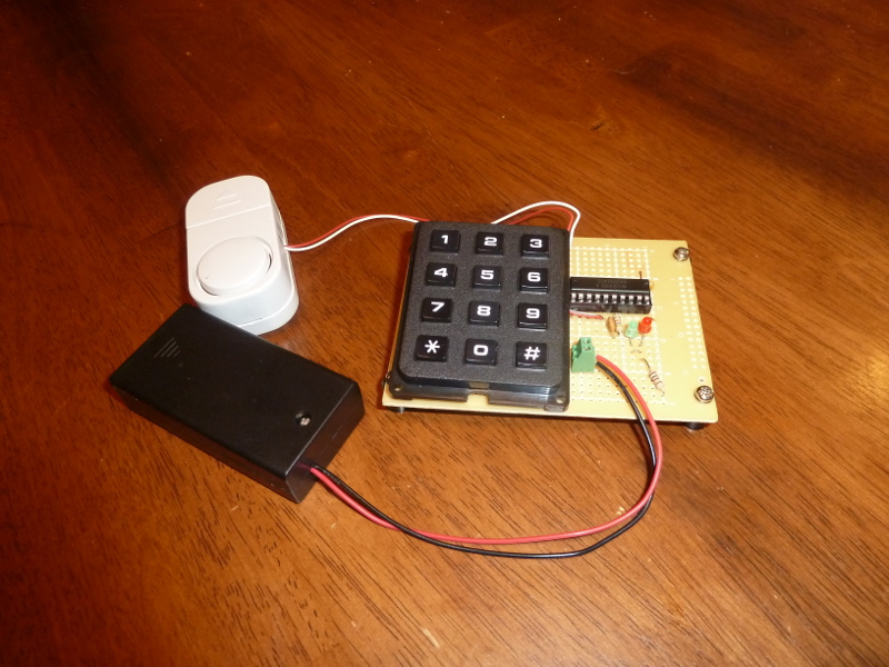
Components in the picture:
-
One Radio Shack prototyping board
-
One Radio Shack 2-AA battery box.
-
One piezo speaker and transformer from http://www.dealextreme.com/p/wireless-entry-alarm-826
-
One TI MSP430G2452
-
One 20-pin DIP socket
-
One Jameco keypad (part number 2081828)
-
One 0.1uF capacitor (between Vcc and GND)
-
One 0.001uF capacitor (between RST and GND)
-
One 47k ohm resistor (between RST and Vcc)
-
Two 3mm LEDs (anodes on pins p2.6 and p2.7)
-
One 100 ohm resistor (between cathodes of LEDs and GND)
-
One terminal block for power
1. Keypad control
My first tasks were to get the LEDs to light, and to get usable input from the keypad. The LEDs were fairly easy after accounting for one detail. They are hooked to p2.7 and p2.6, but those pins also double as XIN and XOUT (if you use an external clock crystal). Clearing the P2SEL bits for those pins, changes their behavior to standard I/O pins.
They keypad was a bit more work. For one thing, it didn’t come with any kind of data sheet or instructions. So I had to take it apart and follow the traces to see how the 10 wires of the keypad are controlled by the 12 keys. These are the wire connections I discovered:
-
black — 1 — blue
-
white — 4 — blue
-
violet — 7 — blue
-
black — 2 — green
-
white — 5 — green
-
violet — 8 — green
-
black — 3 — yellow
-
white — 6 — yellow
-
gray — 9 — yellow
-
violet — 0 — yellow
-
orange — * — red
-
brown — # — red
They configuration is not as efficient as it could be (3 wires for columns and 4 wires for rows would be better), but it is what it is. I decided to consider the 6 colors on the left of my list to be "supply" wires, and the 4 colors on the right are "receive" wires. I connected blue, green, yellow, and red wires to pins on Port 2, p2.1-p2.4 respectively. That way I can detect keypresses by asserting a voltage on one supply wire and letting that trigger a corresponding interrupt on the Port 2 interrupt handler. The black, white, gray, violet, orange, and brown wires are connected, respectively, to Port 1 pins p1.0-p1.5.
Since I envision this burglar alarm as battery powered, I’d like it to sleep in the lowest power modes as much as possible. For that reason, in the code that follows, I have configured the auxilliary clock to use the Very Low-power Oscillator (VLO), and I trigger the Watchdog timer interrupt from that every 44 milleseconds. The Watchdog interrupt handler charges each of the keypad supply wires briefly (with interrupts re-enabled) so the Port 2 handler can trigger.
For reliability, I chose to use two successive triggers as the definition of a keypress and two successive misses as the definition of a key release. This worked very well. I don’t get accidental "doubles," yet the pad is responsive.
Here’s my first set of sample code. It lights both LEDs, briefly, each time a key is pressed.
#include <msp430g2452.h>

// Port 1 connections to the keypad.
#define KEY_BLACK  BIT0
#define KEY_WHITE  BIT1
#define KEY_GRAY   BIT2
#define KEY_VIOLET BIT3
#define KEY_ORANGE BIT4
#define KEY_BROWN  BIT5

// Port 2 connections to the keypad.
#define KEY_BLUE   BIT1
#define KEY_GREEN  BIT2
#define KEY_YELLOW BIT3
#define KEY_RED    BIT4

// Port 2 has LED status lights and reed switch.
#define REED_SWITCH BIT0
#define LED_GRN    BIT7
#define LED_RED    BIT6

// Port 1 has the piezo speaker.
#define SPEAKER0   BIT6
#define SPEAKER1   BIT7

#define NUM_KEYS   12
char key_symbol[NUM_KEYS] = { '0', '1', '2', '3', '4', '5', '6', '7', '8', '9', '*', '#' };
char key_pressed[NUM_KEYS] = { 0,0,0, 0,0,0, 0,0,0, 0,0,0 };
char key_pending[NUM_KEYS] = { 0,0,0, 0,0,0, 0,0,0, 0,0,0 };
char p1_color[NUM_KEYS] = { KEY_VIOLET, KEY_BLACK, KEY_BLACK, KEY_BLACK,
    KEY_WHITE, KEY_WHITE, KEY_WHITE, KEY_VIOLET, KEY_VIOLET, KEY_GRAY,
    KEY_ORANGE, KEY_BROWN };
char p2_color[NUM_KEYS] = { KEY_YELLOW, KEY_BLUE, KEY_GREEN, KEY_YELLOW,
    KEY_BLUE, KEY_GREEN, KEY_YELLOW, KEY_BLUE, KEY_GREEN, KEY_YELLOW,
    KEY_RED, KEY_RED };
volatile int clear_key_light = 0;

void main( void ) {
    // Stop the watchdog timer
    WDTCTL = WDTPW + WDTHOLD;

    // Set chip to calibrated 1mhz clock rate.
    BCSCTL1 = CALBC1_1MHZ;
    DCOCTL = CALDCO_1MHZ;

    // Set the auxiliary clock to use the VLO.  We'll use this to wake up
    // via the watchdog and scan for keypresses.
    BCSCTL3 |= LFXT1S_2;

    // Set all keys initially to low, but as output pins.
    P1OUT &= ~( KEY_BLACK + KEY_WHITE + KEY_GRAY  + KEY_VIOLET + KEY_ORANGE + KEY_BROWN );
    P1DIR |=    KEY_BLACK + KEY_WHITE + KEY_GRAY  + KEY_VIOLET + KEY_ORANGE + KEY_BROWN;

    // Set piezo leads to low, but as output pins.
    P1OUT &= ~( SPEAKER0 + SPEAKER1 );
    P1DIR |=    SPEAKER0 + SPEAKER1;

    // Set LED status lights off, but as output pins.
    P2SEL &= ~( LED_GRN + LED_RED );
    P2OUT &= ~( LED_GRN + LED_RED );
    P2DIR |=    LED_GRN + LED_RED;

    // Set pull down resistors on port 2 pins that monitor keypad.
    P2DIR &= ~( KEY_BLUE + KEY_GREEN + KEY_YELLOW + KEY_RED );
    P2OUT &= ~( KEY_BLUE + KEY_GREEN + KEY_YELLOW + KEY_RED );
    P2REN |=    KEY_BLUE + KEY_GREEN + KEY_YELLOW + KEY_RED;
    // Interrupt on rising edges.
    P2IES &= ~( KEY_BLUE + KEY_GREEN + KEY_YELLOW + KEY_RED );

    // Set pull up resistor on port 2 pin for reed switch.
    P2DIR &= ~( REED_SWITCH );
    P2OUT |=    REED_SWITCH;
    P2REN |=    REED_SWITCH;
    // Interrupt on falling edges.
    P2IES |=    REED_SWITCH;

    // Enable interrupts for all of the port 2 pins we monitor.
    P2IE |=     KEY_BLUE + KEY_GREEN + KEY_YELLOW + KEY_RED +
                REED_SWITCH;

    // Set watchdog timer to trigger every 16*32.768k/12k = 44 ms.
    WDTCTL = WDT_ADLY_16;
    // Clear the watchdog timer interrupt flag.
    IFG1 &= ~WDTIFG;
    // Enable watchdog interrupts.
    IE1 |= WDTIE;

    /* Do nothing...forever */
    for( ; ; ) {
        /* Go into low power mode 3, general interrupts enabled */
        __bis_SR_register( LPM3_bits + GIE );
    }
}

// Handle key pad symbols.
void do_key( char c ) {
    // Visually signify the press by blinking a light (the reset
    // happens in the watchdog handler).
    P2OUT ^= LED_GRN + LED_RED;
    clear_key_light = 1;
}

void WDT_ISR(void) __attribute__((interrupt(WDT_VECTOR)));
void WDT_ISR(void) {
    int i;

    if( clear_key_light ) {
        P2OUT ^= LED_GRN + LED_RED;
        clear_key_light = 0;
    }

    // Set interrupts on so Port 2 handler can trigger.
    __bis_SR_register( GIE );

    // Turn each wire on in turn to trigger an interrupt on port 2.
    P1OUT |= KEY_BLACK;
    asm( "nop \n\t" "nop \n\t" "nop \n\t" );
    P1OUT &= ~KEY_BLACK;

    P1OUT |= KEY_WHITE;
    asm( "nop \n\t" "nop \n\t" "nop \n\t" );
    P1OUT &= ~KEY_WHITE;

    P1OUT |= KEY_GRAY;
    asm( "nop \n\t" "nop \n\t" "nop \n\t" );
    P1OUT &= ~KEY_GRAY;

    P1OUT |= KEY_VIOLET;
    asm( "nop \n\t" "nop \n\t" "nop \n\t" );
    P1OUT &= ~KEY_VIOLET;

    P1OUT |= KEY_ORANGE;
    asm( "nop \n\t" "nop \n\t" "nop \n\t" );
    P1OUT &= ~KEY_ORANGE;

    P1OUT |= KEY_BROWN;
    asm( "nop \n\t" "nop \n\t" "nop \n\t" );
    P1OUT &= ~KEY_BROWN;

    // Decrement the counts in key_pending[] and record any key releases.
    for( i = 0; i < NUM_KEYS; i++ ) {
        if( key_pending[i] ) key_pending[i]--;
        if( !key_pending[i] ) key_pressed[i] = 0;
    }

    // Clear the watchdog timer interrupt flag.
    IFG1 &= ~WDTIFG;
}

/* Port 2 interrupt service routine.  Triggered by presses of
 * the keypad or by opening of the reed switch.
 */
void Port_2 (void) __attribute__((interrupt(PORT2_VECTOR)));
void Port_2(void) {
    int i;
    int mask = 0;

    for( i = 0; i < NUM_KEYS; i++ ) {
        if( P2IFG & p2_color[i] ) {     // Check if this color triggered the interrupt.
            mask |= p2_color[i];

            if( P1OUT & p1_color[i] ) { // Check if the other color for this key is also on.
                if( key_pending[i] && !key_pressed[i] ) {
                    key_pressed[i] = 1;

                    do_key( key_symbol[i] );
                }

                key_pending[i] = 2;     // Remember for next time.
            }
        }
    }
    // Clear interrupt flag.
    P2IFG &= ~mask;

    if( P2IFG & REED_SWITCH ) {
        P2IFG &= ~REED_SWITCH;
    }
}
At this point, I don’t have a reed switch, though there is code there that will eventually trigger on that. I also haven’t made use of the piezo speaker in this code, though it operates on Port 1 pins p1.6 and p1.7.
The key_pending[] array is how the code checks that a key has triggered on two successive interrupts before registering a key press (and how it checks that a key has failed to trigger on two successive timer interrupts for a key release). In Port_2() it is set to 2 each time a key triggers, and in WDT_ISR() it is decremented.
This code was built with msp430-gcc version 4.5.3 and installed:
$ msp430-gcc -O2 -mmcu=msp430g2452 -o keypad.elf keypad.c
$ mspdebug rf2500 "prog keypad.elf"